Spring 2018 3DoT Hexy: Mechanical Drawings (Preliminary/Final)
By: Eduardo De La Cruz (Project Manager and Manufacturing Engineer)
Approved by: Miguel Garcia (Quality Assurance)
Table of Contents
Introduction
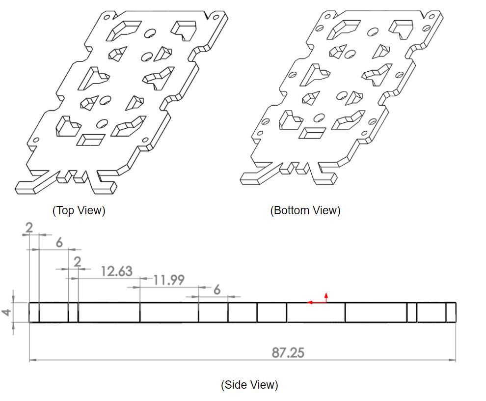
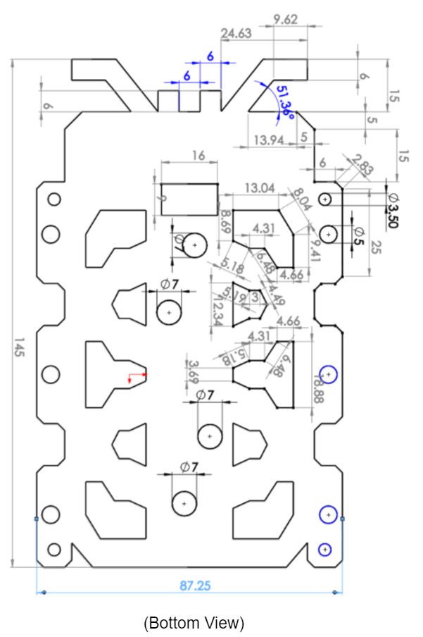
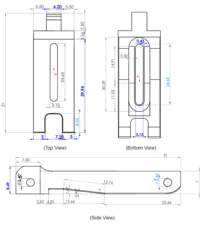
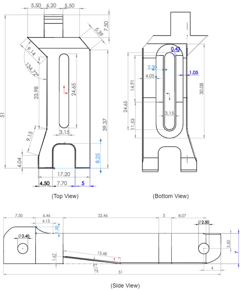
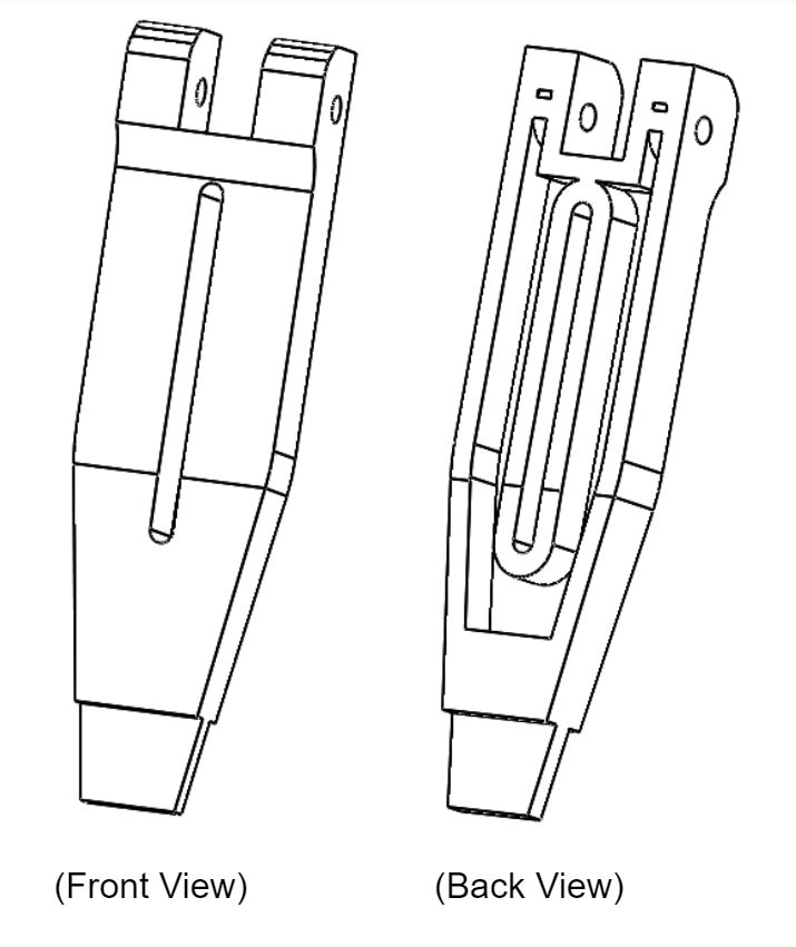
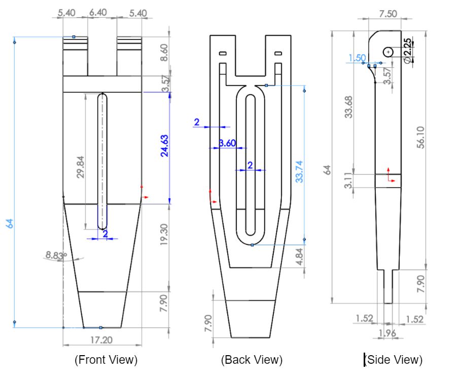
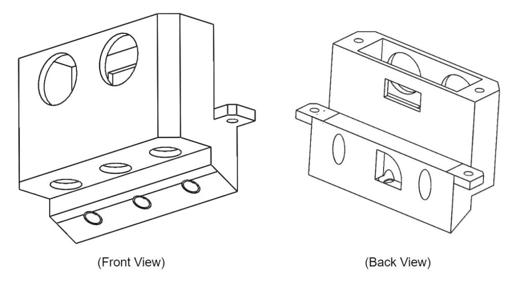
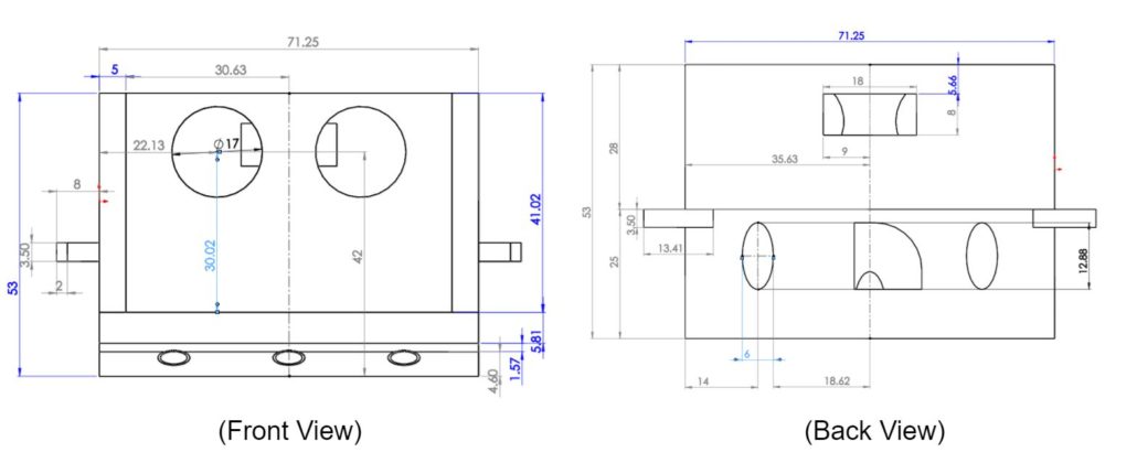
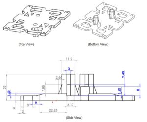
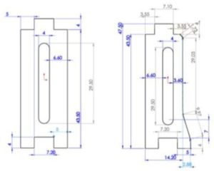
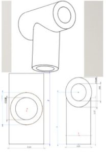
Below are the sketches for our 3DoT Hexy design. Sketches are susceptible to change. All changes will be logged in this blog post in future iterations. The first iteration will be considered our preliminary design which we label as 3DoT Hexy Mk-01. Future revisions will be labeled as iteration “n”: 3DoT Hexy Mk-0n. Note this blog post does not contain reasoning or explanation for why things look the way they are, for that you should read Spring 2018 3DoT Hexy: 3D Model. This blog post just contains the dimensions of all components that will be 3D printed.
3DoT Hexy Mk-02 (Final Design) – (April 28, 2018)
Chassis
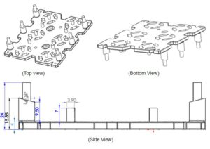
Bottom Panel
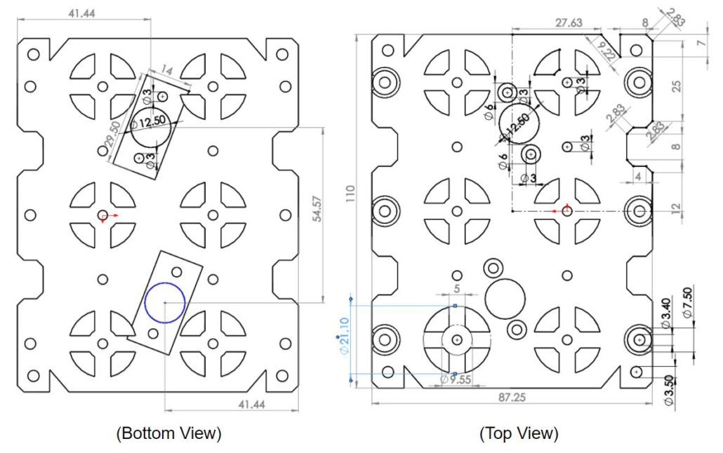 Figure 1: Bottom Plate Dimensions
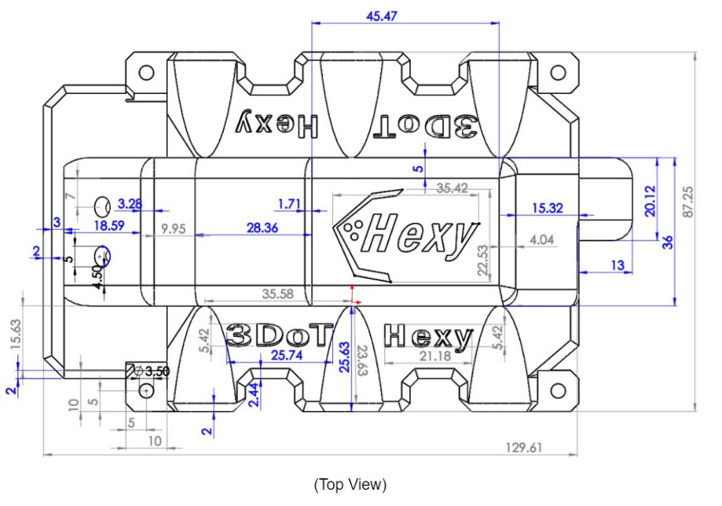
Top Panel
Figure 2: Top Plate Dimensions
Femurs
3 Types of Femurs
Figure 3: Three Types of Femurs
Middle Femur Dimensions
Figure 4: Middle Femur Dimensions
Outer Femurs Dimensions
Figure 5: Front Femur Dimensions
Note: The back leg will have the same measurements with extrude-cut on opposite side.
 Figure 6: Side View of femurs split in half showing Leg lifting ramp
Tibias
Femur-to-Gear Joints
Figure 8: Femur-to-Gear Joint Dimensions
Sensors Enclosure
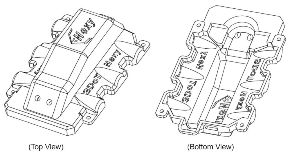
Figure 10: Front and Back View Dimensions
Figure 11: Top and Bottom View Dimensions
Figure 12: Side View Dimensions
Figure 13: Front Split in half view
Hardware Enclosure
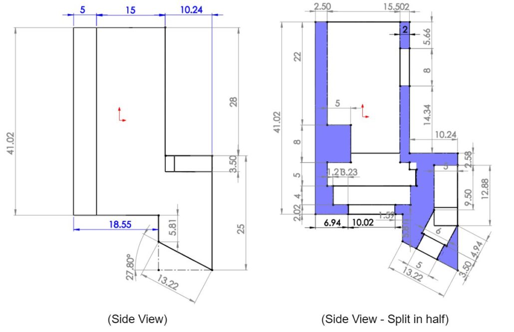
Figure 14: Hardware Enclosure
Figure 15: Side View Dimensions
Figure 16: Top View Dimensions
Figure 17: Split in Half View
Wire Tube
Figure 18: Wire Tube Dimensions
3DoT Hexy Mk-01 (Prototype) – (March 15, 2018)
Chassis
Bottom Panel
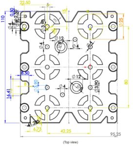 Figure 19: Bottom plate dimensions
Top Panel
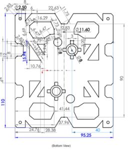 Figure 20: Top plate dimensions
Femurs
3 Types of Femurs
Middle leg Outer Legs
Note: The back leg will have the same measurements with extrude-cut on opposite side.
For all 3 femurs
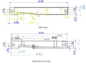 Figure 22: Section view of leg lifting ramp in femurs
Tibias
4 Outer Tibia
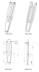 Figure 23: Outer Tibia Dimensions
2 Inner Tibia
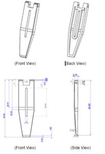 Figure 24: Inner Tibia Dimensions
T-Joints (Gear-to-Femur Joints)
The T-Joints will connect the gears to the femur using 2.5 mm screws


