Spring 2018 3DoT Hexy: Power Estimate of Micro Metals
By: Kris Osuna (Electronics & Control Engineer)
Verified by: Eduardo De La Cruz (Project Manager and Manufacturing Engineer)
Approved by: Miguel Garcia (Quality Assurance)
Table of Contents
Introduction
We obtained two unidentifiable DC motors from Professor Hill’s resource cabinets. Current and Voltage measurements were obtained using an Arduino Uno and INA3221 Breakout Board. Measurements were taken with a load that is half the weight of 3DoT, 66.3g, and the gears in motion. We purchased two DFRobot FIT0481 micro metal gear motors and began our testing.
Components Needed
- Scale
- 3DoT David
- 3 micro metal gear motors
- INA3221 breakout board
- Arduino Uno
- Opto-Reflective switch
- 2 NPN transistors
- Resistors 100, 200, 1k
- Process Control Student Guide by Parallax INC
Related Requirements
- The micro metal motor must be able to turn six gears
- The motor must be able to work in the 3.7-5V range
- The motor must have an RPM of at least 360 with a 66.3g load
Setup
A riser was placed on the scale and tared so that we can weigh 3DoT David shown in figure 1. 3DoT David weighs 132.6 grams. There are two micro metal motors used so each motor will have a load of 66.3 g. The original motor inside 3DoT David was removed. The motors were connected to the INA3221 breakout board to measure current with no load. Set up can be seen in figure 2. RPM was calculated by using the opto-reflective switch to read the black marked paper on the sheet attached to the motor shown in figure 3. The motor spins the attached piece of paper, which is half black and half white. The opto-reflective switch has an IR LED and phototransistor which is able to differentiate the black and white part of the paper. Each count means a full rotation was achieved. The motor shaft was marked black and recorded for 10 seconds then played in slow motion to confirm that the opto-reflective switch readings were correct.
The motor being tested replaced the motor inside 3DoT David. This is done so that the gears moving would be part of the load. The motors are connected to the INA3221 breakout board to measure the current while dealing with the load. RPM was calculated by using the opto-reflective switch to read the black on the sheet taped to the gear attached to the motor. The gear attached to the motor was marked, recorded for 10 seconds and watched in slow motion to confirm the opto-reflective results were accurate.
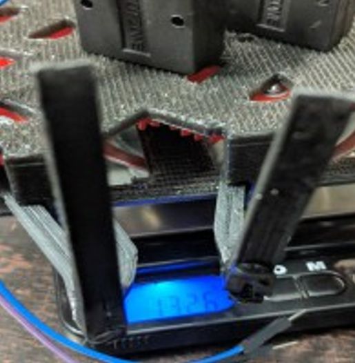 Figure 1: 3DoT David Weight
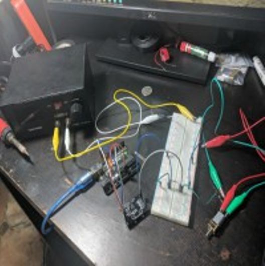 Figure 2: Current Measurement
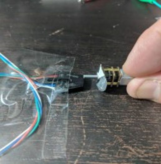 Figure 3: Calculating RPM
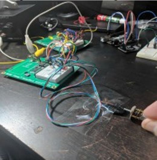 Figure 4: Full RPM measurement set-up
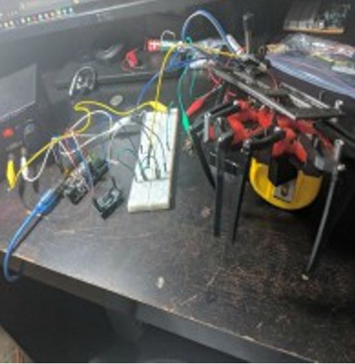 Figure 5: Current measurement with load
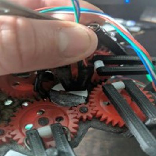 Figure 6: RPM measurement with load
Results

Table 1: Measurements of cabinet motors at 3.7 V
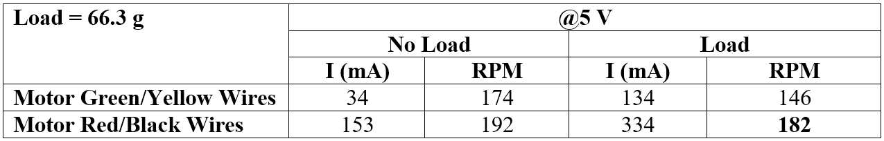
Table 2: Measurement of cabinet motors at 5 V
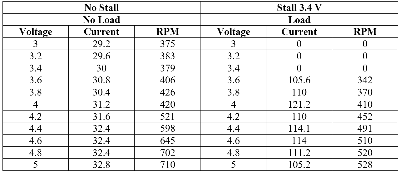
Table 3: Measurements of our purchase motors
The following graph is for table 3 which uses the purchased micro metals that will be used on 3DoT Hexy
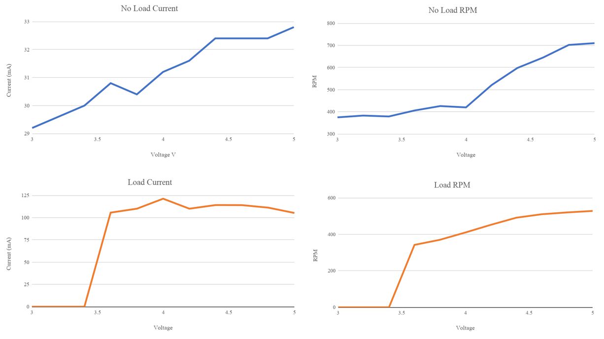
Graph 1: Results from our purchased motors graphed
Analysis
The purchased motors stall at around 3.4 V with a load, because of this it means that we cannot use the 3.3V pins on the Arduino Uno board. The 3DoT board can provide 3.7V to our motors. We are waiting for 3DoT Hexy to be 3D-printed to decide whether we will need 3.7V or 5V power to our motors. Once we find the full weight of 3DoT Hexy with all the sensors attached we should run another power study. The new power study will be more realistic because 3DoT Hexy will be moving and have all the sensors workings. If 3DoT Hexy can take the full load without the motors stalling at 3.7V we would only need one buck booster for the UV LEDs.
Resources
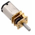
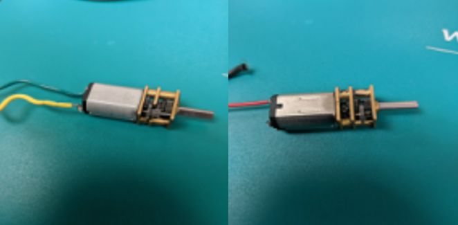 Figure 7: Micro-motors from resource cabinets
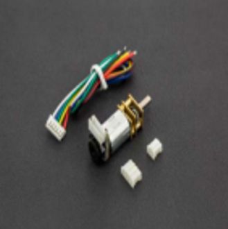 Figure 8: Purchased Micro-motor