Spring 2018 3DoT Hexy: Sensor Shield Layout
By: Kris Osuna (Electronics & Control Engineer)
Verified by: Eduardo De La Cruz (Project Manager and Manufacturing Engineer)
Approved by: Miguel Garcia (Quality Assurance)
Table of Contents
Introduction
This blog contains the sensor shield PCB layout that will be sent out for fabrication. The PCB must contain these parts: I2C multiplex, connection to UV sensors, connection to LEDs connection to ground and power. The UV sensors, LEDs and booster are not going to be directly on the PCB. These items are going to be connected through wires so headers are going to be needed to connect them. Having so many headers provided a unique challenge. The headers take up a lot of space so they must be arranged carefully. I placed all similar headers together to reduce any confusion with silk layer text to clearly identify what sensors go where. It is important to know which sensor is at which header so that the software and hardware can communicate efficiently.
The very first initial draft had many minor issues that first time EAGLE CAD users will encounter. Power and ground routes should have a width of 16 and others have a width 10. I suggest using the polygon tool to create power and ground planes. I did not consider the size and price of the PCB. The first version was very large and very expensive. A helpful tutorial can be found under the resources. I highly suggest working on the schematic and PCB as soon as possible. The PCB will go through many revision before getting a final approval. It is very time consuming and then fabrication takes even longer.
Related Requirements
Level 1 Requirements
- The robot will need to navigate remotely through a custom-built maze (built by AoSa image), memorize the path it took, start over, and autonomously travel through the path it took.
- The robot shall avoid collisions if it encounters other robots while navigating through the maze. This involves detecting the robot, retracing steps back, and moving to a room that allows the other robot to have a safe passage.
- The robot shall use a v6.43 3DoT board.
- The robot shall demonstrate the capabilities of the 3DoT micro-controller for DIY hobbyists.
Level 2 Requirements
- The robot shall use a single RCR123A 3.7 V, 650mA rechargeable Li-ion battery to power the 3DoT board, which will power the drivetrain and all attached peripherals.
- The robot shall use 2 UV sensors connected to a custom PCB.
- The robot shall use a HC-SR04 ultrasonic sensor to handle robot avoidance.
- Ultrasonic sensor shall have a range of 0.5-meter radius to detect and respond accordingly to other robots.
Materials
- Eagle CAD software
Version 4 (April 19, 2018)
Final Sensor Shield Version
Fabian sent me the PCB design back with minor changes and permission to send to fabrication. PCB was sent to Oshpark for fabrication with ‘Super Swift Fab’ option for quicker service. ‘Super Swift Fab’ was chosen because we are running out of time, which is why I suggest starting this process as early as possible.
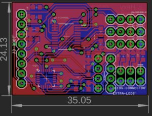 Figure 1: The final PCB design
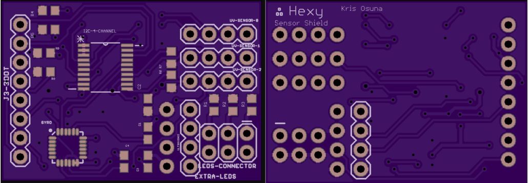 Figure 2: Left: Front of our fabricated PCB, and Right : Back side of our fabricated PCB
Parts:
- 4-Channel I2C
- Gyroscope
- 8-pin header
- Five 4-pin headers
- 6-pin header
PCB now contains these parts: 4-channel I2C, gyroscope, connection to UV sensors, an 8-pin header, five 4-pin headers and a 6-pin header. The 8-pin header will connect to the 3DoT board, which will provide power, ground and four digital pins. Three of the 4-pin headers will connect to the UV sensors. A 4-pin header will connect the ultrasonic. The last 4-pin header will connect two controllable LEDs. The 6-pin header will connect to 3 LEDs. All headers are now labeled to reduce confusion. Waiting for approval from Fabian to send to fabrication.
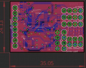 Figure 3: Sensor shield version 3
Version 2 (April 09, 2018)
Parts:
- 4-Channel I2C
- Gyroscope
- 8-pin header
- Five 4-pin headers
- 6-pin header
A gyroscope was added to the design for turns. 5V power was taken out and all power will now come from the 3DoT battery. The 16-Channel I2C is now a 4-Channel I2C to save space and connections. Power and ground planes were added for convenience. The additions of planes reduced a lot of routes and cleaned the design.
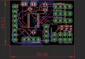
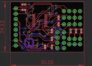 Figure 4: Sensor shield version 2
Version 1 (March 22, 2018)
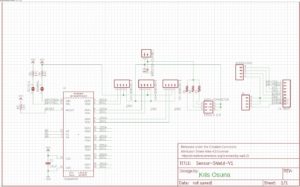
The current PCB is still being worked on. The current schematic image (link 1) and PCB image (link 2) can be found under the links section. The finished schematic and PCB will be upload when they are finished.
Parts:
- 16-Channel I2C
- 8-pin header
- Six 4-pin headers
- 2-pin header
- 6-pin header
Figure 5: Circuit Schematic
Resources

