Spring 2018 3DoT Hexy: Spiderbot Schematic
By: Kris Osuna (Electronics and Control Engineer)
Verified by: Eduardo De La Cruz (Project Manager & Manufacturing Engineer)
Approved by: Miguel Garcia (Quality Assurance)
Table of Contents
Introduction
This blog contains the sensor shield schematic that the PCB will be based on. The schematic must contain these parts: I2C multiplex, connection to UV sensors, connection to LEDs connection to ground and power. The UV sensors, LEDs and booster are not going to be directly to the schematic. These items are going to be connected through wires so headers are going to be needed to connect them. We are getting digital pins from J3 which will be going to connect to the 3DoT. The powerI tried to make the schematic as clear as possible so the viewer can understand what is happening and which sensors are connected or related. Libraries for each product were easy to find online.
Related Requirements
Level 1 Requirements
- The robot will need to navigate remotely through a custom-built maze (built by AoSa image), memorize the path it took, start over, and autonomously travel through the path it took.
- The robot shall avoid collisions if it encounters other robots while navigating through the maze. This involves detecting the robot, retracing steps back, and moving to a room that allows the other robot to have a safe passage.
- The robot shall use a v6.43 3DoT board.
- The robot shall demonstrate the capabilities of the 3DoT micro-controller for DIY hobbyists.
Level 2 Requirements
- The robot shall use a single RCR123A 3.7 V, 650mA rechargeable Li-ion battery to power the 3DoT board, which will power the drivetrain and all attached peripherals.
- The robot shall use 3 UV sensors connected to a custom PCB.
- The robot shall use a HC-SR04 ultrasonic sensor to handle robot avoidance.
- Ultrasonic sensor shall have a range of 0.5-meter radius to detect and respond accordingly to other robots.
Update 3: Sensor Shield V3 ( April 10, 2018)
Parts
- 4-Channel I2C
- Gyroscope
- 8-pin header
- Five 4-pin headers
- 6-pin header
Schematic now contains these parts: 4-channel I2C, gyroscope, connection to UV sensors, an 8-pin header, five 4-pin headers and a 6-pin header. The 8-pin header will connect to the 3DoT board, which will provide power, ground and four digital pins. Three of the 4-pin headers will connect to the UV sensors. A 4-pin header will connect the ultrasonic. The last 4-pin header will connect two controllable LEDs. The 6-pin header will connect to 3 LEDs. I added resistors to the digital LEDs.
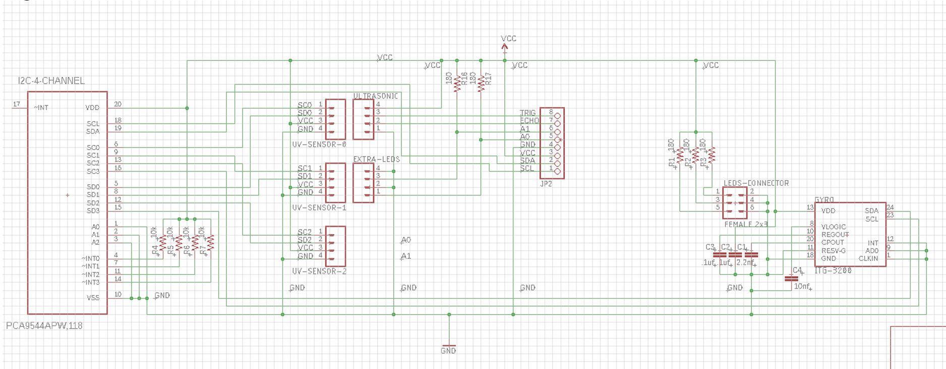 Figure 1: Sensor shield schematic version 3
Update 2: Sensor Shield V2 ( April 03, 2018)
Parts
- 4-Channel I2C
- Gyroscope
- 8-pin header
- Five 4-pin headers
- 6-pin header
A gyroscope was added to the design. The gyroscope will help identify when the robot has made a turn. The 5V power was taken out and all power will now come from the 3DoT battery. The 16-Channel I2C is now a 4-Channel I2C to save space.
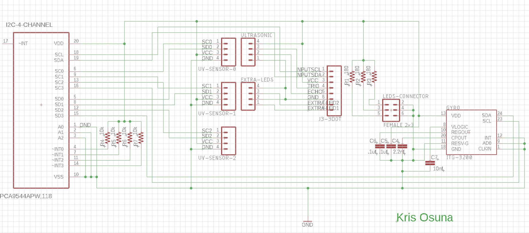
Figure 2: Sensor shield schematic version 2
Update 1: Sensor Shield V1 ( March 22, 2018)
Parts
- 16-Channel I2C
- 8-pin header
- Six 4-pin headers
- 2-pin header
- 6-pin header
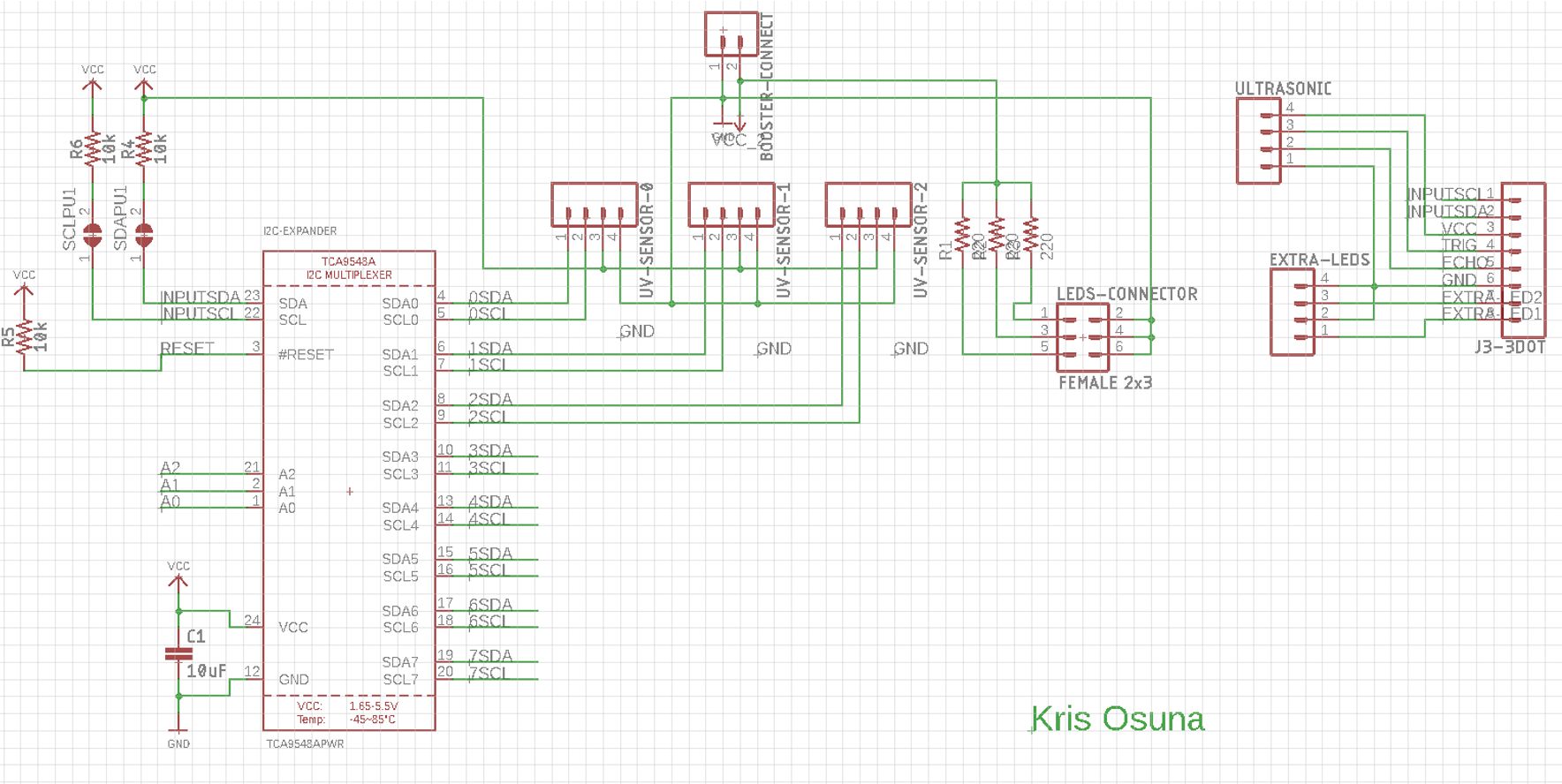
Figure 3: Sensor shield schematic version 1