Spring 2018 3DoT Hexy: System Block Diagram
By: Raymundo Lopez-Santiago (Mission System and Test)
Verified by: Eduardo De La Cruz (Project Manager and Manufacturing Engineer)
Approved by: Miguel Garcia (Quality Assurance)
Table of Contents
Introduction
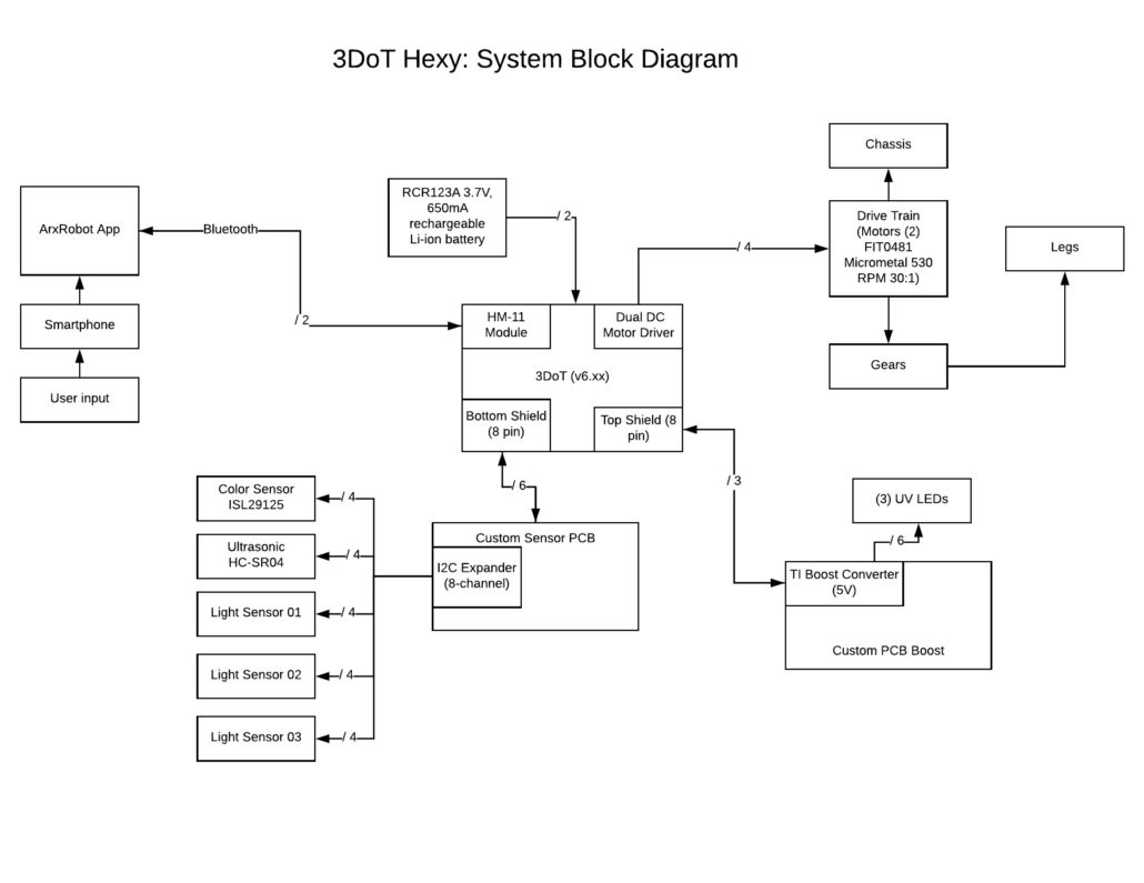
This blog post covers 3DoT Hexy’s System Block Diagram. The 3DoT Hexy robot along with all its peripherals will be powered from a single 3.6V RCR123A battery. The 3DoT board will connect to all other devices. The 3DoT board comes equipped with a BLE Bluetooth module, Dual DC motor driver and (3) 8-pin connections to attach peripherals. Communication for mobile operation of 3DoT Hexy will be done using a BLE Bluetooth module which will be paired to the ArxRobot application. Two separate custom PCBs will be designed and sent for fabrication. The custom sensor PCB will have an I2C expander which will incorporate all sensors which include the color, ultrasonic, and light sensor. The custom Boost Converter PCB to provide 5V to the micro metal motors used to drive the gears/cam-system as well as three UV LEDs. Fig. 1 shows the system block diagram for 3DoT Hexy.
Update 04/17/18
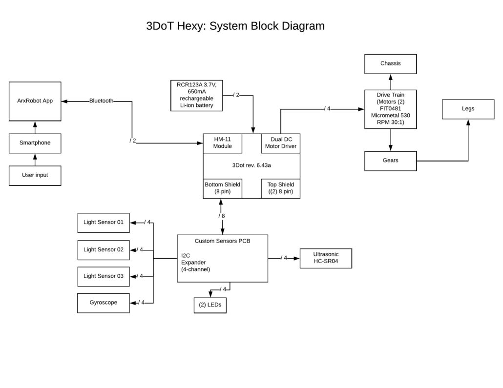
Due to changes in the maze printing material and the fact that we are no longer using a boost converter, the UV LEDs will no longer be used and instead IR LEDs along with Light sensors will be used to handle intersection detection. Another change that is noticeable is instead of using an 8-channel I2C expander, we are now using a 4-channel I2C expander. The color sensor was removed from the design since we are using light sensors for intersection detection. A new addition to the design is the use of a gyroscope to aid in directional turning and two LEDs to act as eyes of the spider robot. The interface matrix was updated to reflect changes. Fig. 2 shows the updated system block diagram for 3DoT Hexy. Only 8-pins from the bottom shield of the 3DoT board will be used.
Fig. 1: 3DoT Hexy Updated System Block Diagram
Preliminary System Block Diagram (03/15/18)
The system block diagram mimics the interface matrix developed for 3DoT Hexy. The 3DoT Hexy system block diagram below shows the different parts of the robot and how they interact with each other. A total of 9 pins out of the 16 pins available from the 3DoT board will be used for the custom PCB’s. The two custom PCB’s will be designed and built to add an I2C expander which will connect to all sensors, also a boost converter to provide 5V to the motor driver. 3DoT Hexy will be powered from a single 3.6V RCR123A battery. Communication for mobile operation of 3DoT Hexy will be done using the HM-11 bluetooth module. Any changes will be added as needed.
Fig. 2: 3DoT Hexy System Block Diagram
Conclusion
The system block diagram is designed taking in consideration of the 3DoT board as the main board to control any attached devices. Visually the system block diagram helps identify connections between devices and how many pins will be allocated or needed. The interface matrix and system block diagram were developed around the same time. I highly recommend to pair these two tasks very close to each other.


