Spring 2018 3DoT Hexy System Cable Tree
By: Raymundo Lopez-Santiago (Mission, System, and Test) & Kris Osuna (Electronic and Controls)
Verified by: Eduardo De La Cruz (Project Manager and Manufacturing Engineer)
Approved by: Miguel Garcia (Quality Assurance)
Table of Contents
Introduction
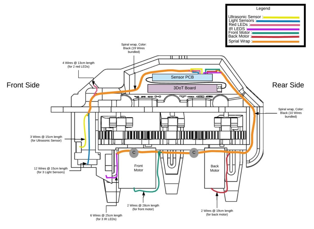
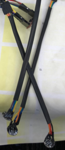
This blog post covers 3DoT Hexy’s cable tree design. 3DoT Hexy will use a total of 29 wires to connect to peripherals from the custom sensor PCB. The final cable tree design is shown in Fig. 1 (side view). The orange lines indicate the use of black spiral wrap protective sheathing which provides cable protection and flexible routing for all wires used. The rest of the wires (ribbon) are bundled according to their routing destination with black shrink tube. An example is packaging 4 wires (SDA, SCL, 3.3V, and GND) for each light sensor. See Fig. 2 for a visual.
Update May 08, 2018
Fig. 1: Side view of 3DoT Hexy: Cable Tree (colored using Lucidchart)
Ten wires will be bundled inside spiral wrap and routed to the bottom part of the robot for the two micro metal motors and the three IR LEDs. Nineteen wires will be bundled inside spiral wrap and routed to the top part of the robot for two red LEDs, an ultrasonic sensor, and three light sensors. Wire clips will be used keep spiral wrap intact while routing wires for peripherals. This is represented as gray dots in Fig. 4.
Fig. 2: Package of 4 wires (SDA, SCL, 3.3V, and GND) for each light sensor
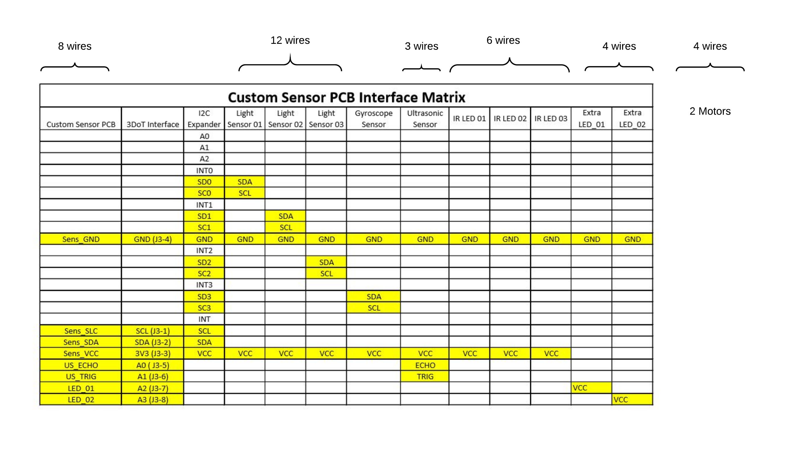
 Fig. 3: Final decision on wire designation
The 3DoT board will have female type connector (8 pins) to connect to the custom PCB sensor board’s 90-degree connector (8 pins). The gyroscope sensor and 4-channel I2C expander are integrated into the custom sensor PCB. The rest of the peripheral devices with information on length and number of wires used are as follows:
- Adafruit Light Sensor Si1145 (x3) – 12 wires @ 15 cm length
- Parallax Ping Ultrasonic Sensor (x1) – 3 wires @ 15 cm length
- Red LEDs (x2) – 4 wires @ 13cm length
- Micro Metal motor FIT0481(x2) – 4 wires @ 19 cm and 28 cm length
- IR LEDs (x3) – 6 wires @ 25 cm length
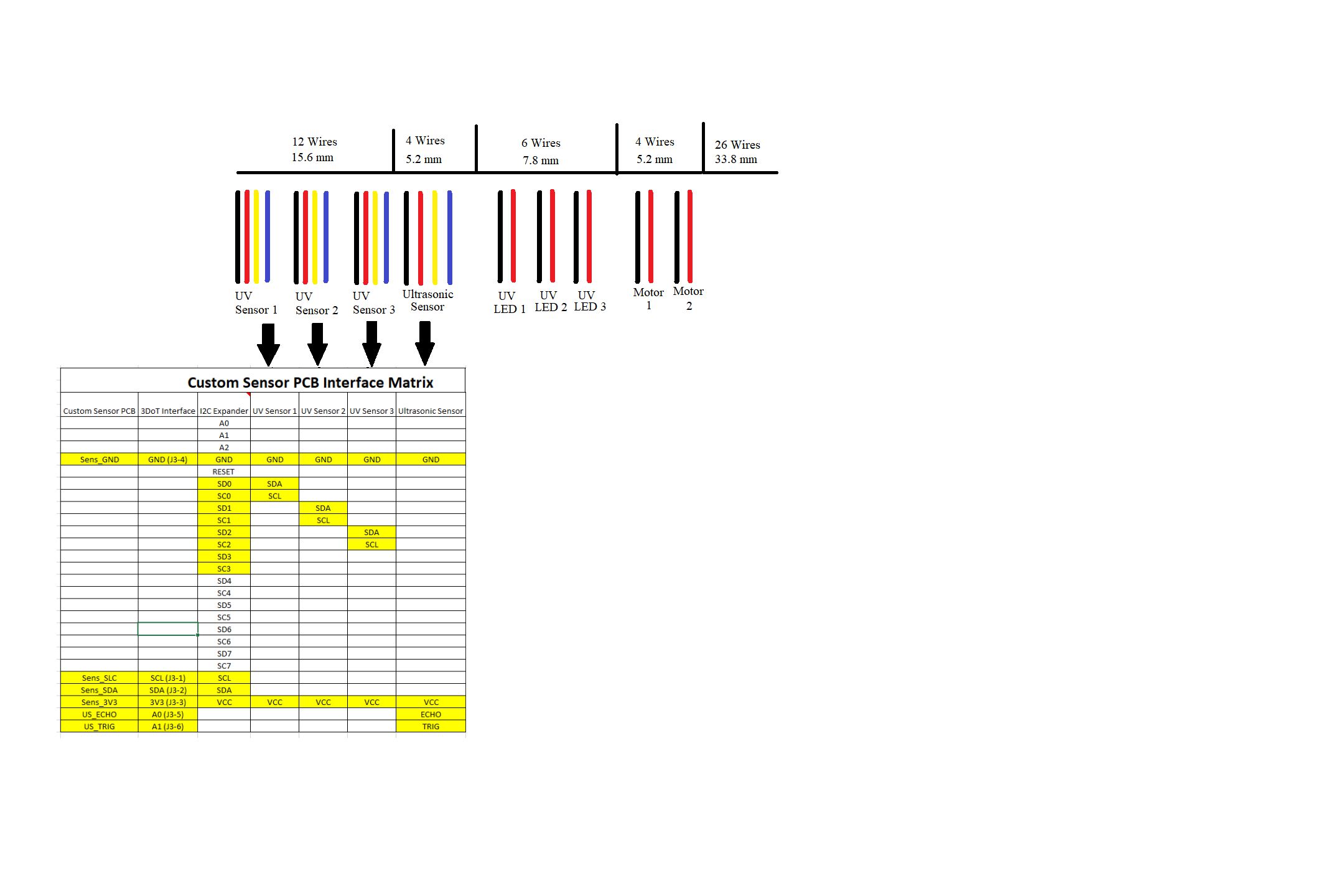
In Fig. 4, the initial wire designation for each peripheral device used is shown. In that revision, a total of 26 wires was to be used. After exploring other design solutions, a final representation for 3DoT Hexy’s peripherals with the number of wires used can be seen in Fig. 1.
 Fig. 4: Initial wire designation approach
Conclusion
Based on our design, it did require a lot wires which caused some issues when integrating all of them to their final position/destination. One main problem was with the positioning of the three-light sensors. A recommendation for a design improvement is to integrate the light sensors into the custom sensor PCB and place the PCB at bottom front bracket. The issue that needs to be further looked at is the 30-degree angle needed for the IR LEDs and the positioning so they maintain that angle. Another recommendation is start the design of the robot by first thinking about the wiring route and possibly integrating 3D printing wire assist clips to ease in the final product wiring.


