Spring 2018 3DoT Hexy: UV Sensors Study
By: Kris Osuna (Electronics & Control Engineer)
Verified by: Eduardo De La Cruz (Project Manager and Manufacturing Engineer)
Approved by: Miguel Garcia (Quality Assurance)
Table of Contents [hide]
Introduction
The original idea for the autonomous navigation of the maze was to have 3DoT Hexy take a picture, process the image and decide its action based on the image. The camera idea was proven to be too extensive with a high learning curve, so we are researched other methods for the autonomous part of the maze. We have decided to look into UV sensors to detect and follow a UV marker line.
Requirements
- Must detect the presence of the UV marker line
- Must be able to differentiate between UV marker line and no UV marker line
Materials
Update 4 (April 19, 2018)
We are no longer using 5V to drive the LEDs. We changed UV LEDs to IR LEDs since the data shows that the UV sensors can not accurately differentiate when the UV LEDs are powered by 3.3V.
Update 3 (April 1, 2018)
Some samples were obtained that should have UV ink. In a similar way as Update 2, data was measured at different spots on the samples.
Data
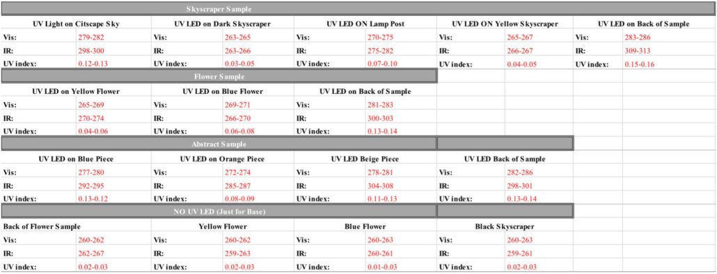
Table 1: UV light test under different UV ink surfaces
Samples containing UV ink data.
All samples were taken with UV LEDs at 5V. It did not look like there was much UV print on the skyscraper sample. The light post seemed to have the most UV ink, because of how it illuminates under UV light. The data shows that the values for the lamp post are lower than the values for the light blue sky. The dark skyscraper has lower values than the lamp post, so the sensor can tell the difference between dark and light. The overall trend in all the data is that the UV sensor is working more like a color sensor. This is somewhat expected since lighter colors reflect more light. We expected the UV marker or UV ink to have a bigger impact on the reflection, but it did not. This might be due to the UV ink and UV marker not being the right wavelength for the sensor to pick up. The maze can be made with white and black lines. However, this would be the same as the current maze that is used. We are currently looking at other options.
Update 2 (March 13, 2018)
Performing a field of view test
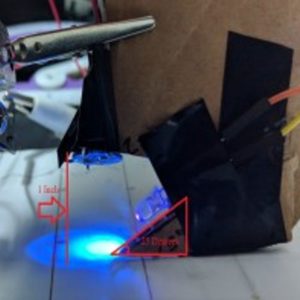
Figure 1: New set-up for measuring values
405 nm LED used at a 25° angle, .7 inch away and .3 inch vertically as seen in figure 1. The calibrated light sensor is 1 inch above the marked line pointing straight down. Two UV LEDs were used at the beginning, but one stopped working. A pack of one hundred 395 nm UV LEDs were ordered to redo the testing with multiple LED testing. Measurements were taken at the center of the UV marked line, at the edge of the marked line then measurements at every half an inch away from the edge until 2 inches away from the edge of the line.
Data
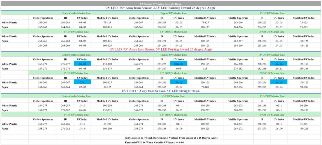
Table 2: UV test results
Conclusion
The data shows that the UV sensor values, when the UV LEDs are driven at 3.3V, is not reliable for detection. The value differences on all materials is very small making detection very difficult. The best values I obtained were on white plastic. The values show that the UV index with a threshold of .06 would best be used. This has a nice drop off that could be used to make the maze.
Update 1 (March 6, 2018)
Test 1
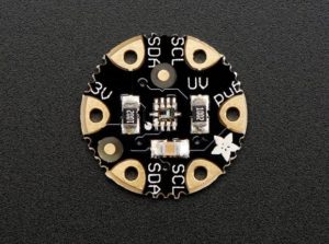
The UV sensors we looked at were the Si1145/46/47 and the SL1145. Once the sensor was received testing was begun immediately. First tests should that the UV marker was not being detected by the UV sensor. Closer reading of the Si1145/46/47 datasheet revealed that the UV reading is not a “true” UV reading. The sensor uses a calibrated light-sensor to find the UV index.
We decided to find a true UV sensor. The sensor we used is the GUVA-S12SD which is an analog “true” UV sensor that reads that detects 240-370 nm wavelengths. The sensor works with voltages of 2.5-5.5V which is within our robot’s range. When the GUVA-S12SD sensor arrived we hit a roadblock. The sensor would not get a reading even with a UV blacklight directly on the sensor. We believe that the UV marker does not give out a wavelength that the sensor can reach. We used a black light to illuminate the UV line and the GUVA-S12SD did not receive any information. We believe this is because the UV marker is not in the 240-370 nm range.
We went back to the Si1145/46/47 with a blacklight directly on top. This gave us a UV index readout. We were able to reverse engineer how they obtain UV index from wavelengths. Our UV index value was multiplied by a constant of 25 then multiplied by 100 to make the value easier to read. The test was performed at two different values 3.3 V and 5 V: 3.3 v is the minimum voltage obtained from a pin read out when we used a multi-meter and 5 V is the voltage if we were to use a booster shield. Blacklight was 1 inch away straight above and tested on a 1 x 1 inch square that was marked by the UV marker. Measuring was started on the UV line and moved out of the UV marked square. Plastic white at 1 inch away seems to give the best results.
UV Light directly on the UV sensor 1500-2300*
*Cloth was Grey 90% Cotton 10% Polyester
Table 3: .5-inch distance results
Table 4: 1-inch distance results
Table 5: 2-inch distance results
Figure 2: Flora UV index sensor – Si1145 light sensor
Figure 3: Analog UV sensor
Figure 4: UV marker
Figure 5: Measuring set-up

