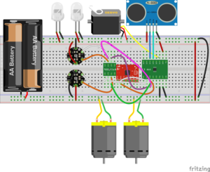
Spring 2018 AT-ST Fritzing Diagram
By: Shweta Hebbalkar (Electronics and Controls – Hardware)
Verified By: Intiser Kabir (Project Manager)
Approved By: Miguel Garcia (Quality Assurance)
Introduction
Fritzing is a tool for the student to create clean and professional images of electronics projects. Building a virtual circuit in breadboard view, using Fritzing, gives a better representation of circuit connection close to the real circuit. Fritzing introduces a user-friendly interface for a quick and easy workflow. A user can build and edit virtual electronic circuits, schematics, or PCBs. The concept is drag and drop; the user can drag and drop components from the part library to the project window. Parts are connected using the breadboard and wires. Wires are created instantly by clicking and dragging a part’s connector. Fritzing software made our life so easy because we can change the color of the wires and make the wires curve or bend them. If I click and hold on the connector, Fritzing will highlight all equipotential connectors. I can also select the schematic and PCB tabs to watch or edit my circuit.
Body
I found all components from the default library; if I could see any parts in the library, I can look in Fritzing official website or Google. Some of the parts I could not find, but lucky in Fritzing, we can make our custom parts, by opening the inspector then selecting the component whose properties that we want to change. Then we complete the circuit by connecting all the connection.
In this figure, I have the 3-DoT board, gyroscope, I2Cexpander, two UV sensor, two IR LEDs, Servo, Ultrasonic, two motors, actually, we are using the micrometer with shaft encoder and 3 volts.
Conclusion
This is a sophisticated tool to use to create a virtual breadboard, and it will help us build it physically. If we miss a connection, then we can always look back and fix any problem.

