Spring 2018 AT-ST Mechanical Drawings
By: Danny Pham (Design and Manufacturing Engineer)
Verified By: Intiser Kabir (Project Manager)
Approved By: Miguel Garcia (Quality Assurance)
Introduction
For our robot to walk and turn successfully, we will be designing elements of the robot that will be able to balance itself and move smoothly. The AT-ST walker design will incorporate parts of the Velociraptor and Biped design from previous semesters. The AT-ST will also incorporate dc motors instead of servos, so we switched out from our previous Titrus III leg design. In our case, our robot designs will be using the Theo Jansen leg design and split leg function that the previous 2017 Spring velociraptor project used.
Concept Sketches
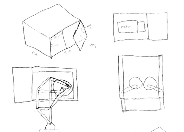
Figure 1: initial sketches and idea of Priliminary Model
Description
For the body of the AT-ST walker, for preliminary design, we will be using a box. The box will have side panels that open and close like a door. The Theo Jansen legs will be attached to the outside of the panel, and the motor will be mounted on the inside of the side panels to connect to the legs. Another set of gears and servos inside the body will move the connector to open and close the doors, which in turn will turn the leg like split leg function.
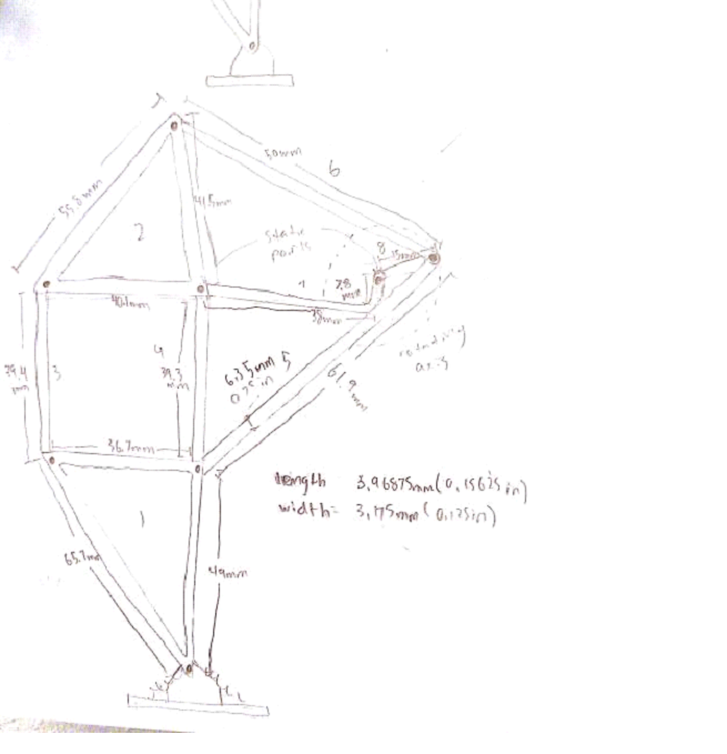
Figure 2: initial ideal measurement of our Theo Jansen Leg
Description
This is the Theo Jansen leg design. The measurements are taken from the actual Theo Jansen leg dimensions. The width that we picked for the leg is 3.175mm because it will be made of carbon fiber and that width is sturdy enough for the carbon fiber material to support the leg.
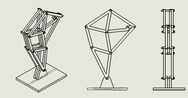
Figure 3: 2D Sketch of Theo Jansen Legs
Description
The leg is structured so that it is not just a one dimensional build of the leg. Each component is doubled so that the leg structure is wider and that will make the leg more stable. The previous velociraptor group also included springs on the feet in order for the foot to not be parallel to the ground at all times. This will help the Theo Jansen leg motion and keep it moving.
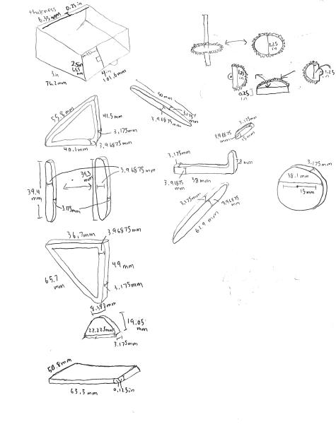
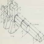
Figure 4: Measurement Parts
Description
These are the individual measurements of each connector in the legs, and other miscellaneous parts in the body.
Conclusion
These will be the basic design of the AT-ST walker robot. The measurements used for the leg design are scaled versions of the actual model and models from the previous semesters to fit our maze and robot definitions. The measurements and shapes are subject to change once we test the function of a rapid prototype of the robot design.