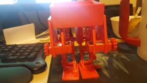
Spring 2018 AT-ST Rapid Prototyping
By: Danny Pham (Manufacturing and Design Engineer)
Verified By: Intiser Kabir (Project Manager)
Approved By: Miguel Garcia (Quality Assurance)
Table of Contents
Introduction
3D printing using a plastic can cause inaccuracies in the dimensions and measurements of the piece that you are printing. Even if the pieces are designed to be simple shapes, dimensions can be skewed because plastic can become deformed while the 3D printer melts the plastic. To counter this, we printed many copies of different pieces. Despite our efforts, pieces continued to be skewed and we had to sand down the pieces in order for the pieces to fit in our prototype.
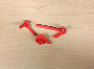
All of the components we printed are not simple shapes. The connectors have small edges and holes that 3D printing can not avoid making inaccuracies for. In order to remedy this, we printed many copies of a few complex pieces with different 3D printer settings to see if a change in accuracy, layers, and density would fix some of these errors. As you can see in the image above, many of the pieces came out very well. Some of the holes and edges in the pieces had to be sanded out in order to fit other pieces, but the main design and function of the pieces was printed correctly.
Printing components
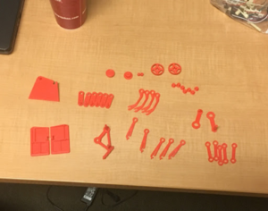
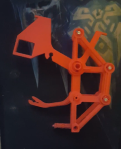
Figure 1: These are the components we printed that will be put together to build the legs of the robot.
We printed the pieces with PLA so the printed components are brittle and easy to break. We had to replace these with new reprints and increased the number of layers and density so that the components weren’t as easy to break when putting the bot together.
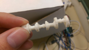
The main piece that gave us the most trouble to print was the rotating shaft. Because it’s design is complex, the shapes are easy to deform. The component was also not flat, so we had to use a more supporting material as a platform for the material to sit on while it was 3D printing. When we printed the rotating shaft vertically, it was very easy to snap. After we changed the 3D printing setting to print it sideways instead of vertical, it was very sturdy yet it looked messy. Changing some accuracy settings allowed us to create a good rotating shaft that looked clean and was sturdy enough to rotate on the robot without breaking.
The first print of the rotating shaft. It is a complex piece to print because of alternating circles and different sizes throughout the shaft. It was also very easy to snap because we printed it vertically.

Figure 4: Future print of the rotating shaft using higher precision settings and sideways printing instead of vertical.
The printed motor case fit the motor pretty well. The only thing I did not account for was having space for the wires to stick out without constraining the motor in the case. A simple solution to fix this was to cut out a bit of the edge on the side so that the wires can stick out while allowing the motor to fit in the case.
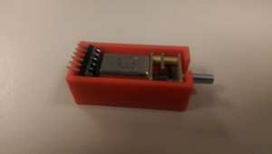
Figure 5: Printed case for the motor to sit in. It contains a hole on the side so the shaft can rotate freely without issue.
The pieces we printed required a lot of sanding just to fit each other. Almost all of the pieces had some inaccuracies in dimensions and shapes because of 3D printing. Some pieces were too big to fit in the holes for other components. We tried modifying the size of the holes and edges on Solidworks for reprinting, to account for 3D printing inaccuracies, and many other issues came up. These issues included having holes too big, dimensions still deformed, and more cost for paying for reprints. We decided that sanding down the components to fit each other would work best in saving money and also fixing the issue of deformities in the components.
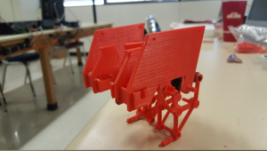
One leg put together after sanding down the pieces. Each component of the leg fit pretty well and the leg moved pretty well. The connections were not too tight or too loose.
We will be designing a new box to fit the ultrasonic sensor, servo, and other electronics.
Conclusion
After putting the components together, the robot came out similar to the Solidworks model. There were some minor errors in the prototype. Some of the pieces were a loose fit instead of snug, but overall, the pieces connected to each other well and the motion of the leg was not disrupted. The shaft rotated cleanly and the leg moved in a Theo Jansen motion as intended.
References
- https://grabcad.com/library/theo-jansen-type-biped-walking-robot-strandbeest-1
- https://drive.google.com/open?id=10GJDTiolPUA9C2i3yNMLMN5Ndx_wRcU-
- Final 3D Model: Linked when blog is published

