Spring 2018: Biped Breadboard Build and Test
Written By: Jorge Hernandez (Electronics & Control)
Verified By: Miguel Gonzalez (Project Manager)
Approved By: Miguel Garcia (Quality Assurance)
Our design ended up being breadboarded which fit inside of Micro FOBO’s head. The reason we had to resort to breadboarding is due to the fact of using a wrong chip. Originally Fobo operated on the CD-4017 decoder chip as we used the PCA9685 16-channel PWM driver on our PCB. Due to this error, in order to move Micro Fobo we need to use the 4017 decoder and with limited time, we breadboarded and tested. In order to build and use the 4017 decoder to drive the 8 micro servos Micro Fobo uses, I drew up a schematic and pinouts to simplify which derive from projectbiped.com.
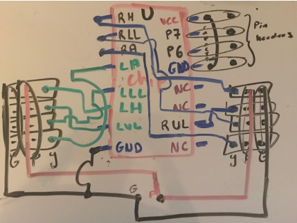
Fig1. Pin Out and connection of 4017 decoder
To clarify figure 1
- RH= PWM connection to Right HIP
- RLL= PWM connection to Right Lower Leg
- RA= PWM connection to Right Ankle
- RUL= PWM connection to Left Upper Leg
- LH= PWM connection to Left HIP
- LLL= PWM connection to Left Lower Leg
- LA= PWM connection to Left Ankle
- LUL= PWM connection to Left Upper Leg
- NC= no connection
- GND= ground connection
- VCC= connection to 5 v
In figure 2 one can see the actual completed breadboard.
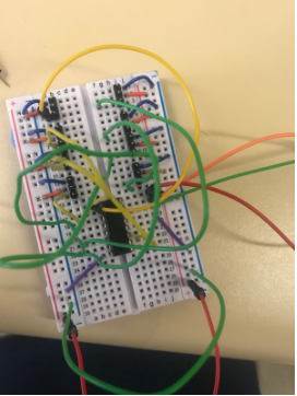
Fig.2 Completed 4017 breadboard connection
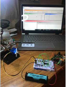
Fig.3 Testing each servo using FOBO Poser
Using this breadboard shield gave us full control of each individual servo when connecting a 4.7 V battery to it. The program used to calibrate was provided by Projectbiped.com which was called FOBO poser. The breadboard build and test were successful when testing individual micro servos. The walking test will be a more challenging task as it uses all 8 micro servos simultaneously.
Below is a video of the actual calibration.