Spring 2018: BiPed PCB Assembly
By: Jorge Hernandez (Electronics & Control)
Verified By: Miguel Gonzalez (Project Manager)
Approved By: Miguel Garcia (Quality Assurance)
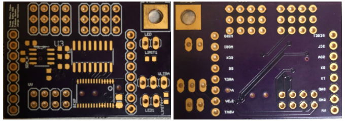
The E&C Engineer, once I constructed Micro FOBO’s PCB, which consisted of a servo PWM expander and 2-channel multiplexer components, the team, and I realized we used the wrong PWM driver. The PCB from Oshpark came out perfectly other than an error which prohibited us to use it which was a shame since we were out of time to order a new PCB. For specifics, our PCB was a 1.58 x 1.10 inch (40.2 x 27.9 mm) 2 layer board.
For the PCB assembly, it was not possible as the parts from DigiKey were the wrong parts or else I would have started the assembly process. The wrong Digikey parts and images that came in can be found here (BOM blog post). For future Biped teams, specifically FOBO, as the E&C who spent all semester learning EagleCad, I suggest using the CD-4017 decoder chip as that is the chip FOBO is supposed to run on according to projectbiped.com. Gerber files of my PCB can be found here (Eagle Cad files) if needed.

