Spring 2018: Biped Software Diagrams
By: Miguel Gonzalez (Project Manager & Manufacturing)
Approved By: Miguel Garcia (Quality Assurance)
One of the most helpful things to do before you start writing code is to create a flowchart and a software block diagram. These diagrams will help you understand the overall construction and function of the code. In this blog post, we will be looking at the diagrams our team created to visualize how the Micro FOBO should function. These charts introduce tasks the software must complete reaching mission success.
Related requirements:
Level 1
L1-12: Micro FOBO shall detect intersections in the maze.
L1-13: Micro FOBO shall be able to perform static walking.
L1-14: Micro FOBO shall to produce 90 degree turn.
L1-15: Micro FOBO shall guide the Micro FOBO through the maze with the use of the Arxterra application.
L1-17: The Micro FOBO shall traverse the maze using the recorded path.
Level 2
L2-5: Micro FOBO shall use the color of the maze to establish if it needs to turn.
L2-10: Micro FOBO shall play a musical tune when the maze is completed.
L2-11: Micro FOBO shall have indicating LEDs to demonstrate either a left or right turn.
L2-16: Micro FOBO shall detect objects 8 inches from it.
L2-17: Micro FOBO should be able to see other robots to avoid collision. Robot will stop completely and
wait for command. (Ultrasonic sensor)
L2-18: Micro FOBO should take a bow at the end of the maze.
Software Block Diagram
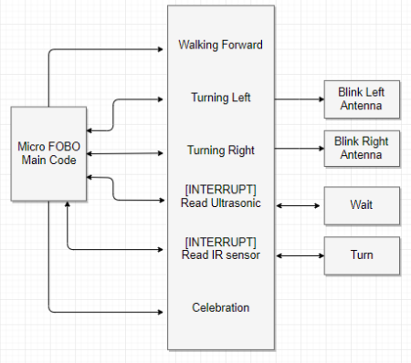
The software block diagram can be thought of as individual code modules that work together to create the overall software system for the Micro FOBO.
As you can see in figure 1 the left block represents the “main code” section. In this section, you will find all the functions and call to functions the robot utilizes for the completion of tasks. This section houses the main code that runs in a loop calling on subroutines to make readings or to simply perform a task. The middle section of the block diagram represents all the available “functions/subroutines” the robot has available. Some functions include Walking forward, turning, and taking measurements. It is clearly visualized from the arrow movement that the main code of FOBO has the ability to call subroutines and functions located in the middle section of figure 1. Finally, looking at the right part of the chart we can see the “actions” section which is the code that runs after certain functions are run. For example, if Turning Left is run then the action of blinking the left LED antenna will be performed.
Software Flow Chart
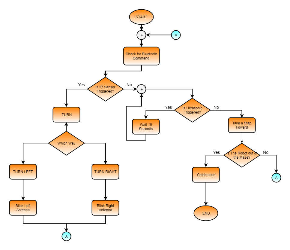
Although the software block diagram is a useful tool for understanding the subroutines and actions of the robot it can still be difficult to use as a template for writing code. For this reason, we make software flow charts. We can use the block diagram above to make the flowchart that you see below.
As you can see, this flowchart is a visualization of how the code runs showing all it’s decision procedures and actions it takes whether its tests are true or false. Instead of reading the chart from left to right like the previous diagram we read this chart from top to bottom. As we can see the first thing the code will do when starting up is check for a Bluetooth command if not command is present it will proceed to check if the IR sensor is triggered. A yes answer will cause the code to run the “turn” function which causes the program to ask “which direction.” Once instructions are received the program will perform the next action and blink the corresponding LED. If the IR sensor is not triggered then it will check the ultrasonic sensor. If triggered, Micro FOBO will assume there is a robot crossing in front of it so it is instructed to wait until it’s cleared. The program will loop back every 10 seconds to check if the path has been cleared. Once cleared the program will proceed to take a step forward. At every step, the robot will ask itself if it has cleared the maze. If the answer is false then the program loops back up to the beginning. It is quite apparent that by using these two diagrams we can fully understand the behavior of the robot and how its code should be written to produce the desired functions. In the next few weeks, our E&C engineer will be utilizing these diagrams to write the code necessary to have Micro FOBO navigate through the maze and achieve all customer requirements.


