Spring 2018: BiPed System Schematics (EagleCAD)
By: Jorge Hernandez (Electronics & Control Engineer)
Verified By: Miguel Gonzalez (Project Manager)
Approved By: Miguel Garcia (Quality Assurance)
Introduction
After the Fritzing design was completed, an EagleCAD schematic has to be designed to create a PCB in order to move the project forward. EagleCAD is a software program that allows the user to place components on the board, and wire all the connections properly. Pins such as I2C pins can be connected across the network
Here I explain the mistakes I have made and my final schematic for Micro FOBO which has been approved by Gary Hill and Fabian Suske.
Requirements
Level 1:
L1-18: Micro FOBO shall utilize a printable Circuit Board (PCB)
L1-7: Micro FOBO will utilize a 3DoT board (PCB will be mounted on 3DoT board)
Previous Schematics
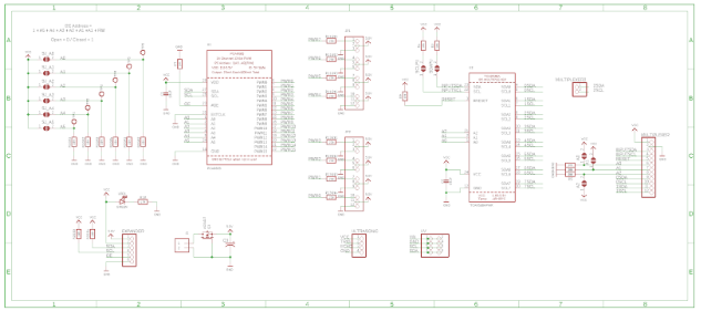
Fig.1 Previous Schematics
For my first rough draft at Micro FOBO’s Eagle schematic, I did not implement the 3 DoT shield pin header which was a huge mistake. The reason this is a mistake is that if I did order this board, it would become a floating board which will require extra wires to connect my custom PCB to the 3DoT. As one can see, I also included the 12C TCA9548A Multiplexer, as the Micro FOBO will use 2 UV sensors which require different addresses to read values from each UV sensor. Using the TCA9548A was a mistake because it takes too much space, as it has the ability for 8 different I2C sensors and all we needed was 2. Another mistake which was making pinouts for the HC-SR04 ultrasonic, as that specific ultrasonic required 5V to operate which would have required a booster shield. A trade study for ultrasonics was done and found that the SEN136B5B ultrasonic sensor operates at 3.3V which eliminates a need for a booster shield as all the other components (UV, LED’s, Multiplexer, PCA Servo Expander) run at 3.3V or less(limiter resistor required).
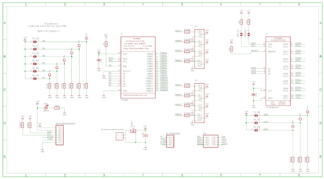
Fig.2 Another Schematic (not approved)
Final Schematic Ordered
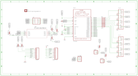
Fig.3 Final Schematic
Instead of individual resistors that protect the PWM of the Servo Expander, Hill suggested a resistor package for routing simplicity and a cleaner look (SO16 package). Another major change was to simply ground all address (A0-A5) on the Servo Expander to use the default address on that chip. 3DoT pin headers were introduced which will make this PCB sit on the 3Dot and not have loose wiring connections between these two boards. Voltage declarations were updated as everything operates at 3.3V other than the 8 Micro Servos, which will operate together, require an outside power source and therefore are connected to VBATT. Changing our multiplexer to the PCA9540BDPN was critical, as it is a 2 channel multiplexer which will save space on the PCB, compared to the 8 channel multiplexer from the previous schematics.
Conclusion
The completed Fritzing diagram and the Eagle schematic move our project closer to mission success. We now have a concrete version of our schematic and how each component is connected to each other. This is then sent to the Manufacturing Engineer and Project Manager to be approved. Once approved, the board layout (routing) will be completed.
References
- https://www.arxterra.com/fall-2016-velociraptor-eaglecad-schematic/
- https://www.arxterra.com/spring-2016-rofi-pcb-design-alternative-arduinos-and-custom-eagle-components/