Spring 2018: BiPed Ultrasonic Sensor Board & Prototype Fritzing Diagram for BiPed
By: Jorge Hernandez (Electronics & Control Engineer)
Verified By: Miguel Gonzalez (Project Manager)
Approved By: Miguel Garcia (Quality Assurance)
Table of Contents
Introduction
From the research performed, the number of ultrasonic sensors required to make a biped
robot is one sensor. We know one sensor will be used which will cause the robot to only
detect objects in a one-directional plane. According to our level 2 requirements, we are using
the ultrasonic HC-SR04 sensor to meet out level two requirements:
Shall be able to see other robots to avoid a collision. The robot will stop completely and wait for
a command. (Ultrasonic sensor). This expands farther:
1. If the sensors are too far from an object, the robot will move forward.
2. If the sensors are too close to an object, the robot should move backward.
3. If the sensors are within the range of an object, the robot will not move.
Types of Ultrasonic sensors
Ultrasonic sensors have a range of 2-450cm (0.78-177in) which will be suitable to track the
other robots from 20 inches away. The way ultrasonic sensors operate is through emitting
sound waves and detecting the sound reflected back from the object. From the reflected
sound, the sensor can provide a measurement of how far an object is away from it. The pros of
ultrasonic sensors are that they can detect objects from farther distances and they can detect
small objects accurately. Also, they can operate in harsh conditions such as dirt. However, they
have slower response times than other sensors, their measurements can be distorted by loud
noises, and surfaces that absorb sound can deter their measurements. The dual cylinder
HC-SR04 is powered up through a 5V source, which will be suitable for our application because
we are using a 5V source coming through the I2C pins of the 3DoT board. The single cylinder
MaxSonar EZ1 Sensor can be powered through a 3V source, which will not be compatible with
our project. This makes the HC-SR04 Sensor the ideal ultrasonic sensor to use in our application.
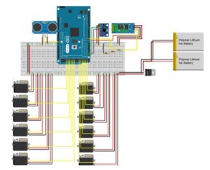
Prototype Fritzing Diagram for BiPed:
The Fritzing application allows a physical breadboard design to be created digitally. By designing
a digital version, the beginning PCB designs can begin. One difficulty with using the free
software is that the library does not have all the parts needed for many designs. Using Google,
many of the parts required were found with Github.
Here are links to the Fritzing libraries for FOBO:
(If using the Adafruit Servo Driver)
(For the Bluetooth Module HC-06 and Accelerometer/Gyroscope MPU-6050)
There was nothing to change at all as we are using the FOBO’s same hardware build. We decided
to go with 2 Lithium Ion batteries, 12 servos, and ultrasonic as well. The color sensor is being
discussed since we know Spiderbot wants to use UV sensors but will be added to fritz diagram
once we know the final maze descriptions.
References
Updated Here: Blog Post

