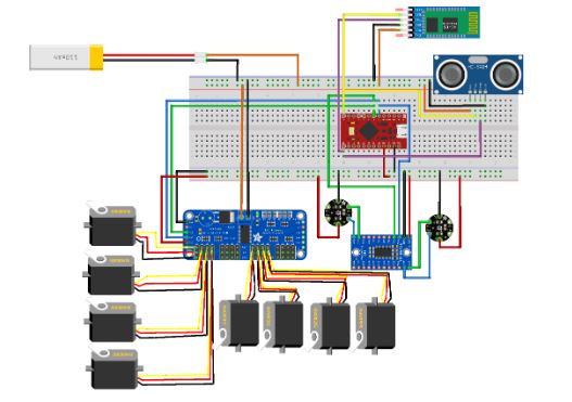
Spring 2018: Updated Prototype Fritzing Diagram
By: Jorge Hernandez (Electronic & Controls Engineer)
Verified By: Miguel Gonzalez (Project Manager)
Approved by: Miguel Garcia (Quality Assurance)
This is an updated Fritzing diagram, especially for Micro Fobo. A PCA9865 servo expander was used because we need to drive 8 micro servos and this expander breakout board lets us use up to 16 micro servos if needed. We only need 8 and that is why 8 headers are empty as they are not needed. A TCS9648A multiplexer board was used as we are using 2 UV’s and they will need different addresses If we want to gather information from them individually. This multiplexer board allows us to have 8 of the same sensor all with different addresses but we will only be using 2. We also have an external power source that will be connected directly to the Ultrasonic that is connected to the Pro Micro. The external power source is also connected to the servo expander and the micro servos will need much more than just 3.3V that is provided from the pro-Micro to run.
References

