The Maze/Spring/2019
Building the Metal Detecting Sensor
Author/s: Alonso Quintero
Verification: Steven Charles Tan (Project Manager)
Approval: Steven Charles Tan (Project Manager)
Table of Contents
Introduction
The metal detecting Sensor is a simple circuit that does an important task. The sensor is made up of a coil that acts as an inductor, a diode and a capacitor. The coils produce an Electro-Magnetic Field and when metal comes in proximity, it disturbs the field sending a signal.
First Iterations
Initially the metal detector was bread boarded with only one coil just to confirm the fluctuations in the voltage when it came in proximity with metal. Once the coil was confirmed to detect metal, two coils were now prototyped as seen in the figure below. Finally, after learning the two coils can work at the same time and not interfere with each other, the PCB was created.
PCB design and various iterations
EagleCAD came in great use in the designing of the metal detecting sensor shield. The 3DoT IR-shield was used as the initial template for this sensor shield. In order to create the spiral traces for the induction coils, the arc tool was used to make the concentric spirals. A grid layout of 10 mils was used in order to allow a maximum number of spirals per coil as well as a two-layer PCB in order to have a two coils on top of each other. Each spiral has a diameter of about an inch. Initially the coils were made with a space of about 25.4mm between the two coils. The wide spacing, however was found to be an issue when it came to line following as the copper tape is only 12.7mm and the robot would have to veer too far off center before it began to read the metal. The coild were then modified to have a 12.7mm spacing between the coils in order to accommodate the copper tape a little better and detect it sooner. Now the robot does not veer to far off before correcting itself.
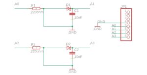
Dual Coil Schematic
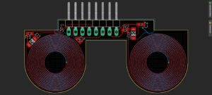
Dual Coil Board Layout
Understanding the Metal Sensor
In order to understand how the sensor was behaving and how to interpret the changes in voltage, the different parts of the sensor had to be tested. The sensor was tested by sending pulses to the sensor. The figure below shows the various phases the different parts of the sensor go through as we send pulses in. through this it was discovered that the inductor saturates after 100 pulses with a 20us period and a 50% duty cycle. Then the energy is bounced between the inductor and the capacitor, allowing for a reading in a change in the magnetic field of the inductor, or coils.
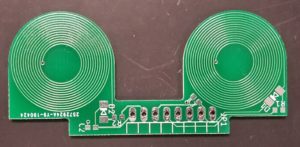
Dual Coil PCB
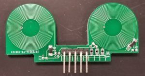
Dual Coil PCB with components
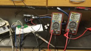
PCB Current test
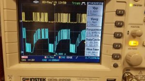
Voltage Input (Top) vs. Voltage Output (Bottom)
Conclusion
The Dual Coil Pulse Induction Metal Detector Sensor can successfully detect metal. From our experiments the sensor-shield is only effective if the conductive material as at most 1 cm below or above the center of the PCB coil, and the closer the material the higher change in output voltage. To improve on later designs the traced coils needs to be closer to one another, an addition of more layers, and a MOSFET needs to be integrated with the design to improve its’ range and increase the range of voltage of the output.