Mod Wheel’s Generation #3
Manufacturing & Design
Mod Wheels/Spring/2020
Spring 2020: Mod Wheel’s Manufacturing & Design
Author/s: Frank Torres (Design & Manufacturing Engineer)
Verification:
Approval:
Table of Contents
Introduction
Mod Wheels Generation #3 began as its predecessor, Mod Wheels Generation #2, that soon had to transform its calm coasting speed to a turbo-boosted daredevil RC car. In order to do so, constraints were immediately met with the chassis size. Our project’s main mission of completing a loop gave me rapid prototyping ideas that I’ll discuss further on. Due to unprecedented events, COVID-19, I was only able to 3D print one chassis before the university shut down. Although I knew I wasn’t going to be able to physically obtain the final chassis I planned on completing this project with, I still created one for future students to use if they plan on upgrading this generation of Mod Wheels.
V1
Originally V1 was the reconstruction of where Mod Wheel’s Generation #2 left-off. Due to the global pandemic our 3Dot board shipment date was postponed and knew we wouldn’t be able to obtain it before of V1 demo. Immediately we decided to use an Arduino Uno that not only was much greater in size than the 3Dot board but also of generation 2’s chassis width. With the aid of our professor we obtained the following from Mod Wheels Generation #1:
- Chassis
- Front Pivot Axle
- Two Front Pivot-to-Wheel Connectors
- Four 42mm x 19mm Wheels
- Two Motor Clamps
The chassis and Arduino Uno measured at 63.5mm x 177.8mm and 68.6mm x 53.3mm respectively proving the chassis and Arduino were compatible; this allowed me to begin assembling our V1.
V1’s Mechanical Components
The mechanical items used for V1 is as followed:
- Chassis
- Front Pivot Axle
- 2x Front Pivot to Wheel Connector
- 4x Wheels 42mm x 19mm
- 2x Motor Clamps
(Off-the Shelf Parts)
- 2x Servo Screws 2mm x 6mm
- 2x Front Pivot to Wheel Connector 2.5mm x 10mm
- 2x Motor Clamps screws 2.5mm x 6mm
- 4x 2.5mm nut
- 2x 2mm nut
How V1 Was Constructed
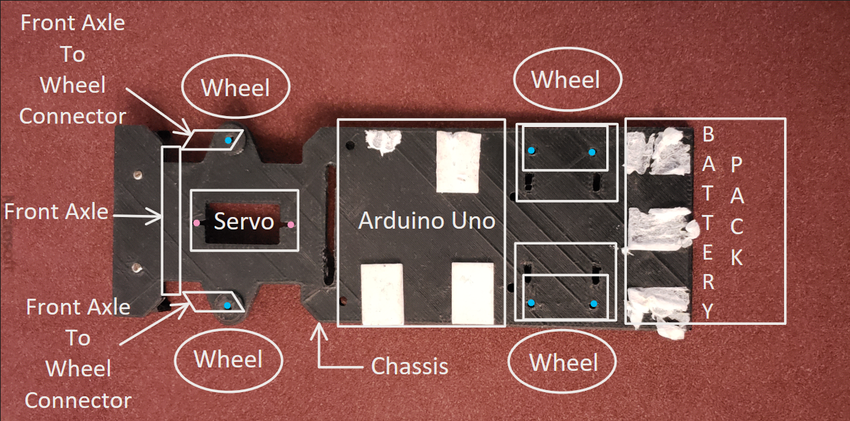
Given all the needed parts, I began constructing our V1. To begin with, I attached the servo by screwing it into place with two 2mm x 6mm screws and tighten with the 2mm nuts. Following, I attached the front pivot axle to the front pivot-to-wheel connectors and then connected it to the servo. To keep the Arduino Uno in place, I placed double-sided mounting tabs where it was set to be put. After securing the Arduino Uno I moved onto installing the motors and did this by using two 2.5mm x 6mm screws and securing the motors with the motor clamps; these clamps were then tightened by 2.5mm nuts. Since the Arduino didn’t contain a power source, we mounted a battery pack behind the motors. The battery pack was way bigger than expected and surpassed the chassis’s available space. With only that available space to work with, I decided to place the battery pack there and kept it in place with double-sided mounting tape. Lastly, I attached all four wheels and V1 was complete. Unfortunately, we didn’t take any pictures of our completed V1 so instead created an annotated image of V1 which included the original V1 chassis that’s displayed in Figure.1
Loop-the-Loop
Completing the loop was our main focus and I knew the dimensions of the V2’s chassis I’m to create would be significant in determining the minimum diameter sized loop and velocity needed for Mod Wheels complete it.
Radius vs Speed Needed to Complete Loop
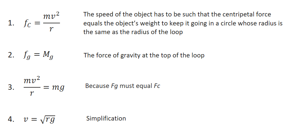
After thorough research I found an equation that’s proportional to the radius and velocity needed to complete it shown in Figure.2.
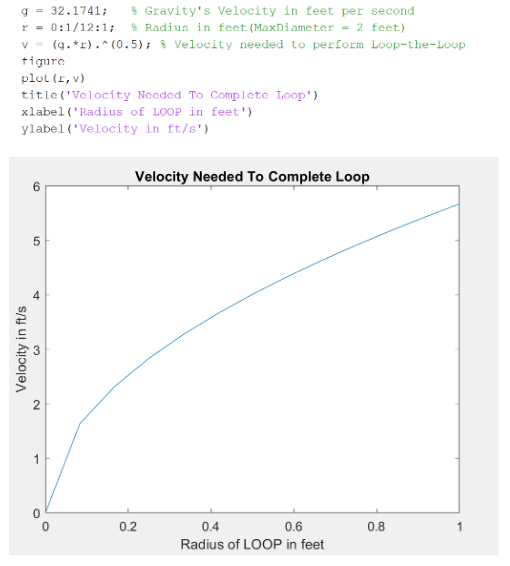
Knowing the equation, I used MATLAB to code and output the velocity and radius needed to complete a loop with the maximum radius of one foot displayed in Figure.3.
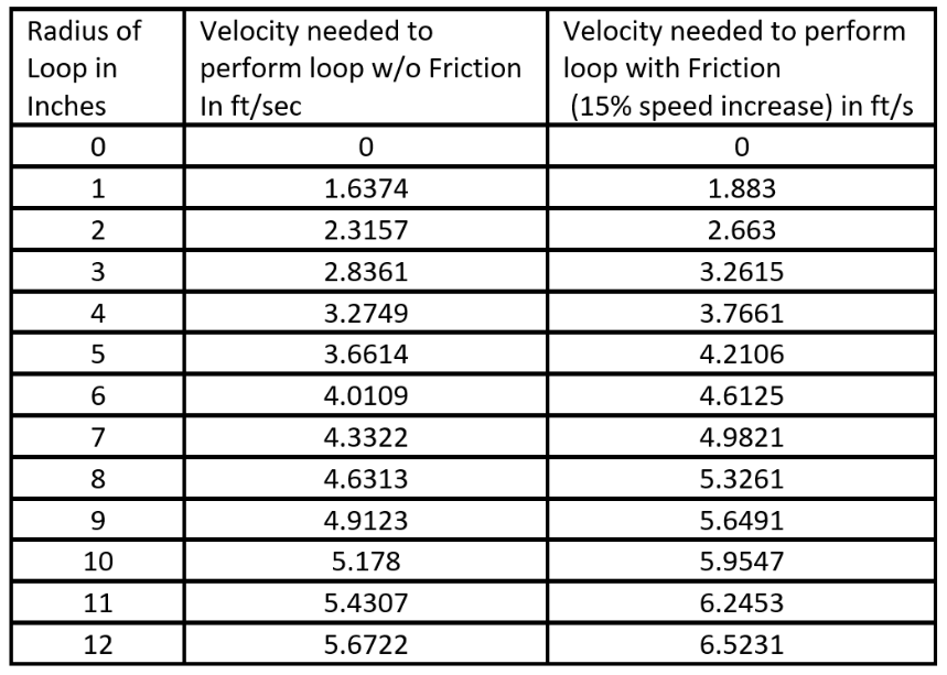
Figure.4 then shows a table showing the velocity needed to complete the loop with respect to velocity.
V2
Knowing that our loop was set to have radius of one-foot max I decided to create the smallest, compacted, yet functional chassis I could think of.
V2’s Rapid Prototyping
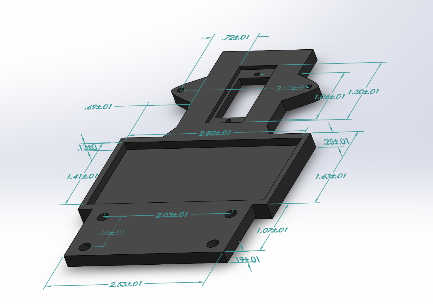
Knowing that the length and width of the 3-Dot board was 70mm x 35mm respectively, I decided I would create a chassis with a max width of 76.2mm in order to create a pocket for the 3-Dot to lay in. Placing the 3-Dot this way saved my chassis from being 35mm longer than if I would have rotated 90 degrees. The amount of space I needed in between motors also became a necessity because the dimensions of the super-capacitor going to be used was 1in x 1in and I planned on putting it there. The reasoning for my last statement is that the capacitor would not fit within the shell of the Mod Wheels if we planned on mounting it on the custom PCB that’s made to attach above the 3-Dot board. The space needed for the 3-Dot in addition with the servo and motor clamp space was about 4 ½ inches or 114.3mm. Now knowing my minimum length and width being 76.2 mm x 114.3mm I began my V2 chassis design using SOLIDWORKS.
V2’s Chassis Design
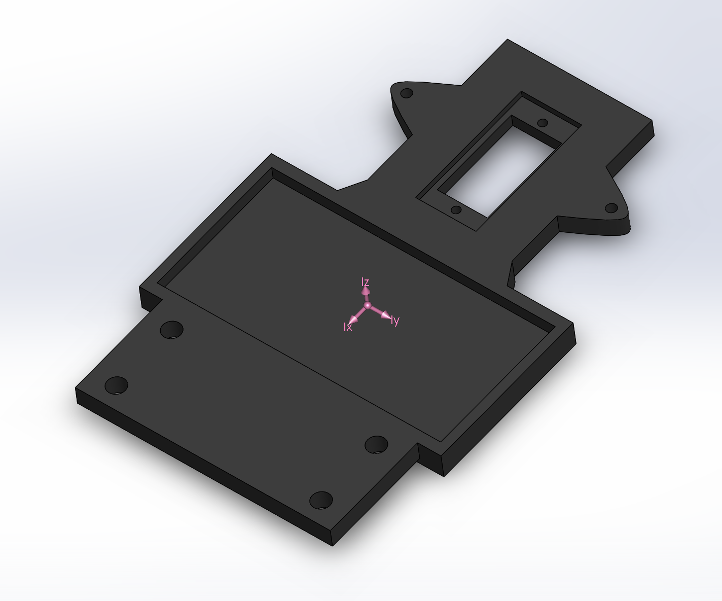
I created a 118.364mm x76.2mm chassis that’s capable of carrying everything needed for. The reduction from V1’s 177.8mm long chassis compared to V2’s length produced a 33% decrease in length. Additional millimeters were added to the front of the chassis to act as a bumper to protect the front pivot axle from being hit if the car were to have a head-on collision with an object. The pocket created for the 3-Dot is Since our project will potentially be crashing into objects because of the stunts having to be performed I decided that the material will consist of carbon-fiber and ONYX in addition with thicken most of the chassis to prevent it from breaking apart.
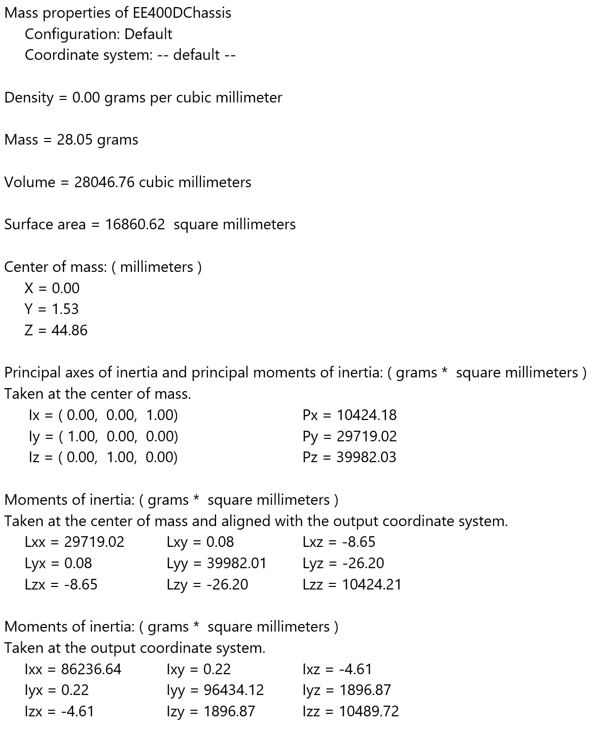
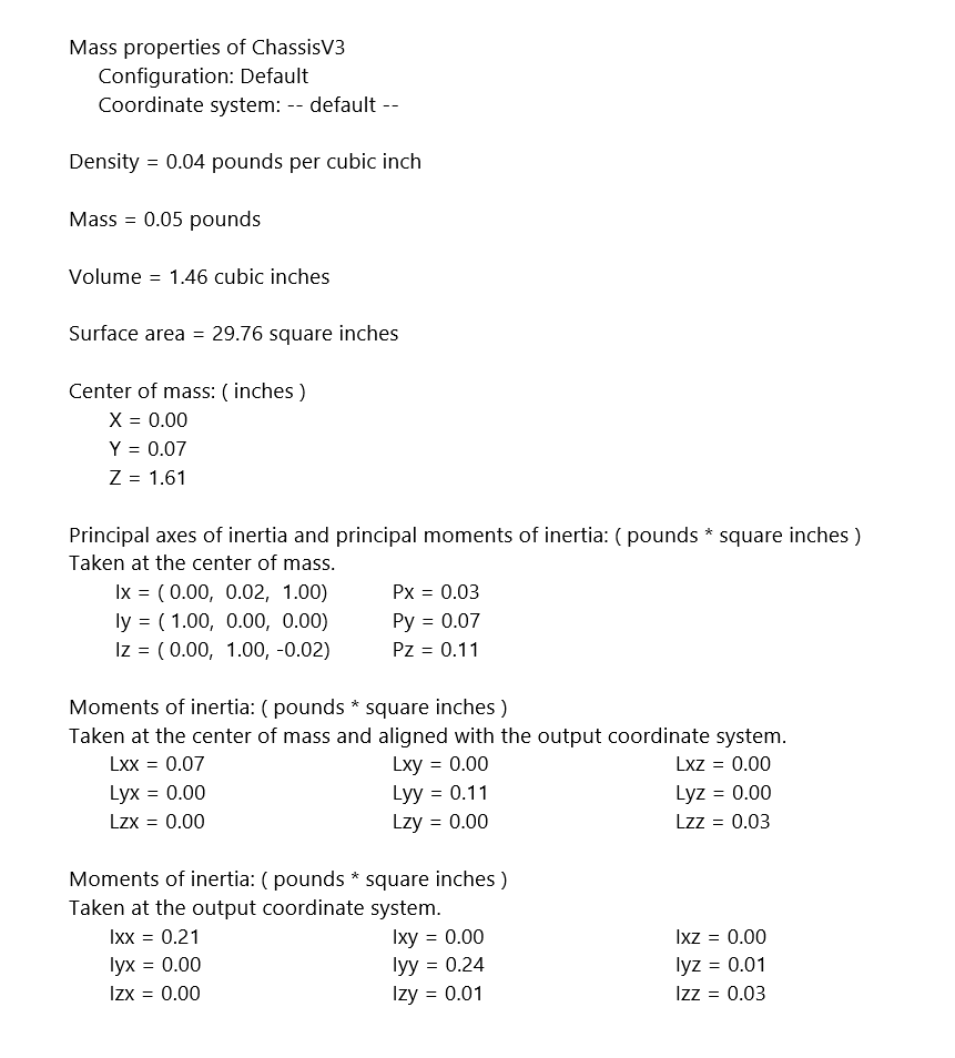
V2’s Mass Properties
V2’s Mechanical Components
The mechanical items used for V2 is as followed:
- V2 Chassis
- Front Pivot Axle
- 2x Front Pivot to Wheel Connector
- 4x Wheels 42mm x 19mm
- 2x Motor Clamps
(Off-the Shelf Parts)
- 2x Servo Screws 2mm x 6mm
- 2x Front Pivot to Wheel Connector 2.5mm x 10mm
- 2x Motor Clamps screws 2.5mm x 6mm
- 4x 2.5mm nut
- 2x 2mm nut
- Double Sided Mounted Tabs
How V2 Was Constructed
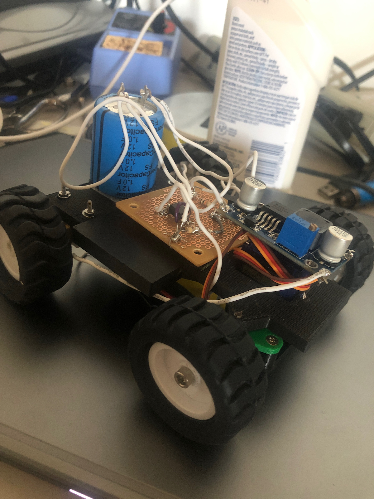
Like V1, I began constructing our V2. To begin with I attached the servo by screwing it into place with two 2mm x 6mm screws and tighten with the 2mm nuts. Following, I attached the front pivot axle to the front pivot-to-wheel connectors and then connected it to the servo. To keep the 3-Dot in place, I placed double sided mounting tabs in the pocket created for it. After securing the 3-Dot I moved onto installing the motors and did this by using two 2.5mm x 6mm screws and securing the motors with the motor clamps; these clamps were then tightened by 2.5mm nuts. Since the capacitor is now placed in between the motors I stuck a doubled sided mounted tab and placed it on the bottom of the capacitor. The breadboard and boost converter were then placed above the 3-Dot safely making sure no shorting would occur. Lastly, I attached the all four wheels and V2 was complete.
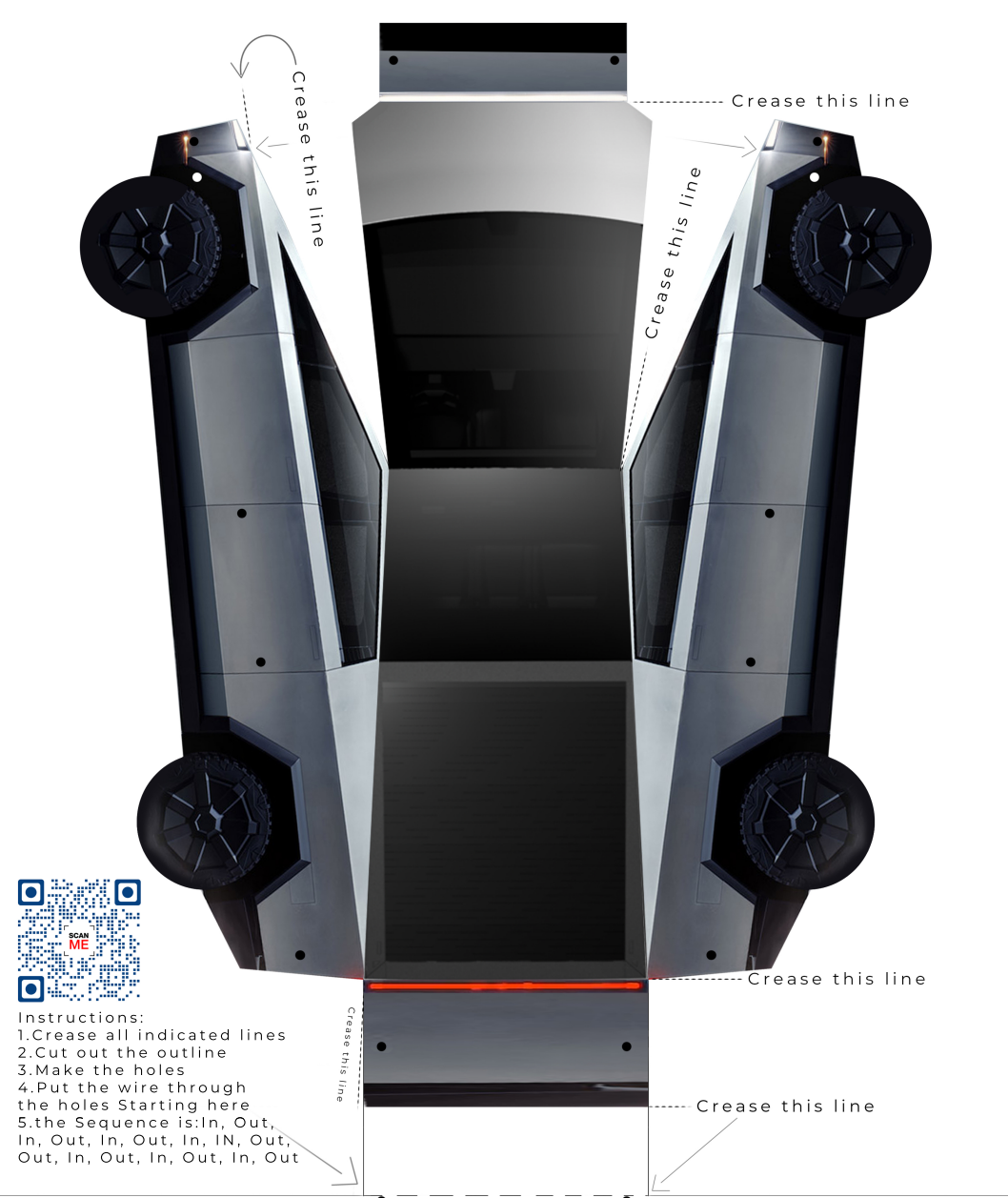
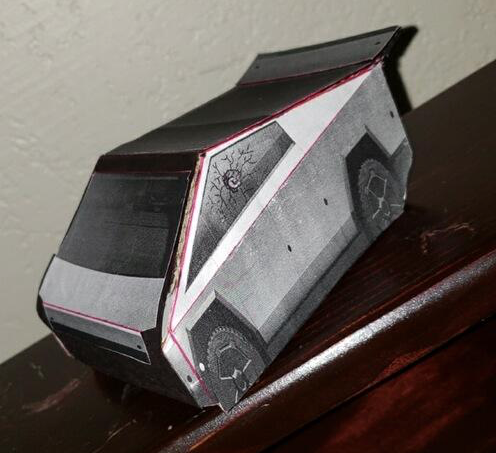
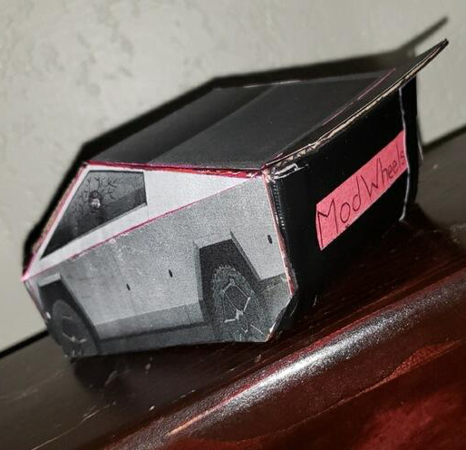
V2’s Cybertruck Shell
The shell intended to secure the components was set to be Tesla’s Cybertruck paper shell. After various ways of trying to design design this shell I came across Cybertruck paper template shown in Figure.9. The finals dimensions of the template produced a 20cm x 10cm x 8cm Cybertruck. In order for this template to work I had to find the ratio regarding the lengths and widths; for this I had to shrink the template length by 42.85% and width by 28.88%. Shrinking the template produced then produced the final shell dimensions of it being 4.5in x 2.8in x 2.25 in.
V3
The closing of our university’s Innovation Space due to the pandemic left us with no choice but you continue using V2’s chassis. Although I would’ve like to make some improvements this chassis would still be good to perform for as our V3 chassis. Those improvements will be later explained. In short, our V’3 about the same as V2 except that I change the rear wheels to be 60mm x 8mm and a custom PCB board will now be substituting the breadboard and boost converter.
V3’s Rear Wheel Changes
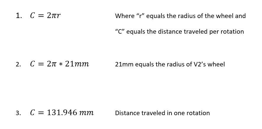
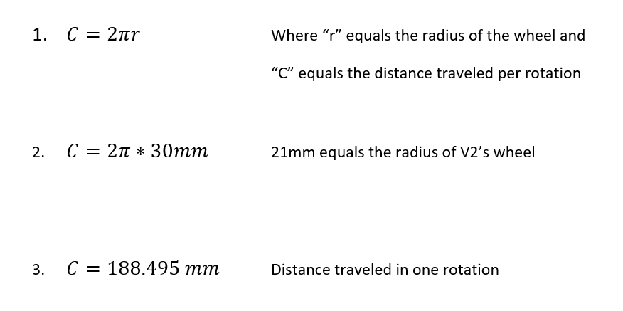
The wheel changes were made by me since V2’s results of not reaching a sufficient speed. An increase in wheel diameter increase the distance traveled by 42.58%. The comparison of distance traveled per rotation is shown in Figure.12 and Figure.13 respectively.
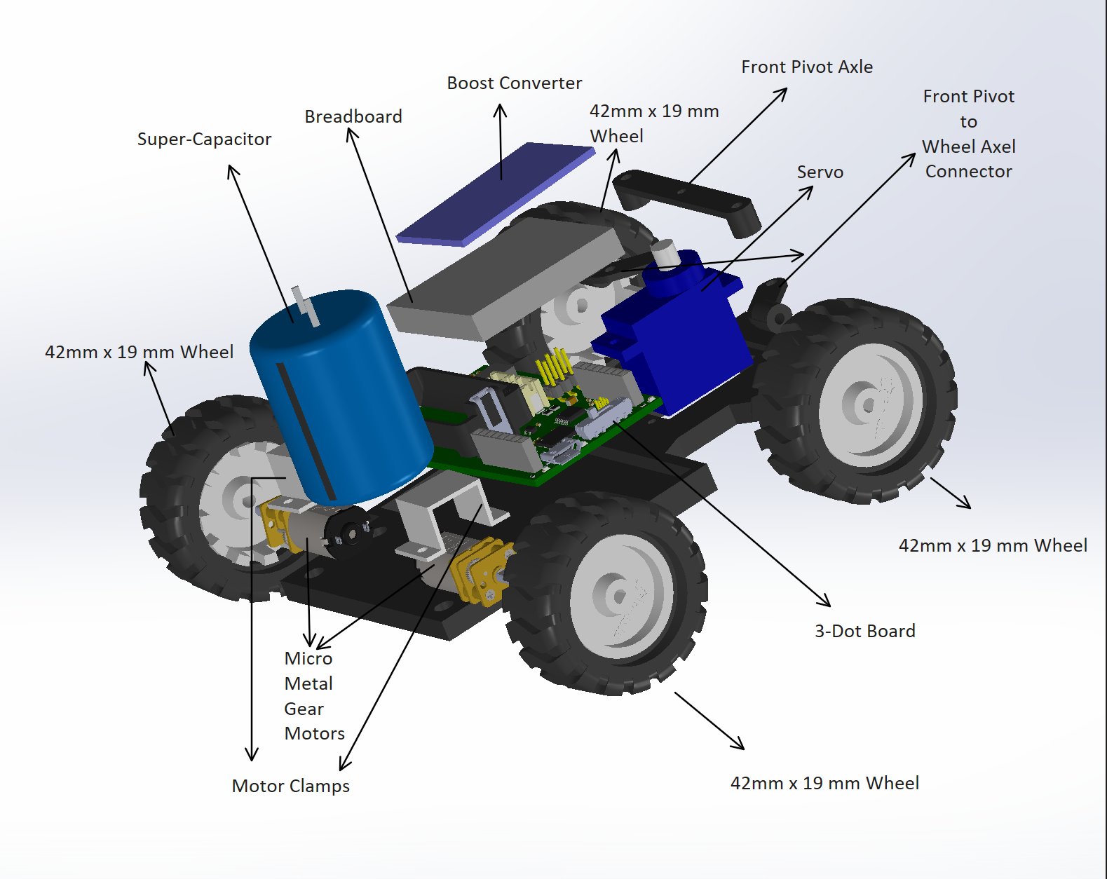
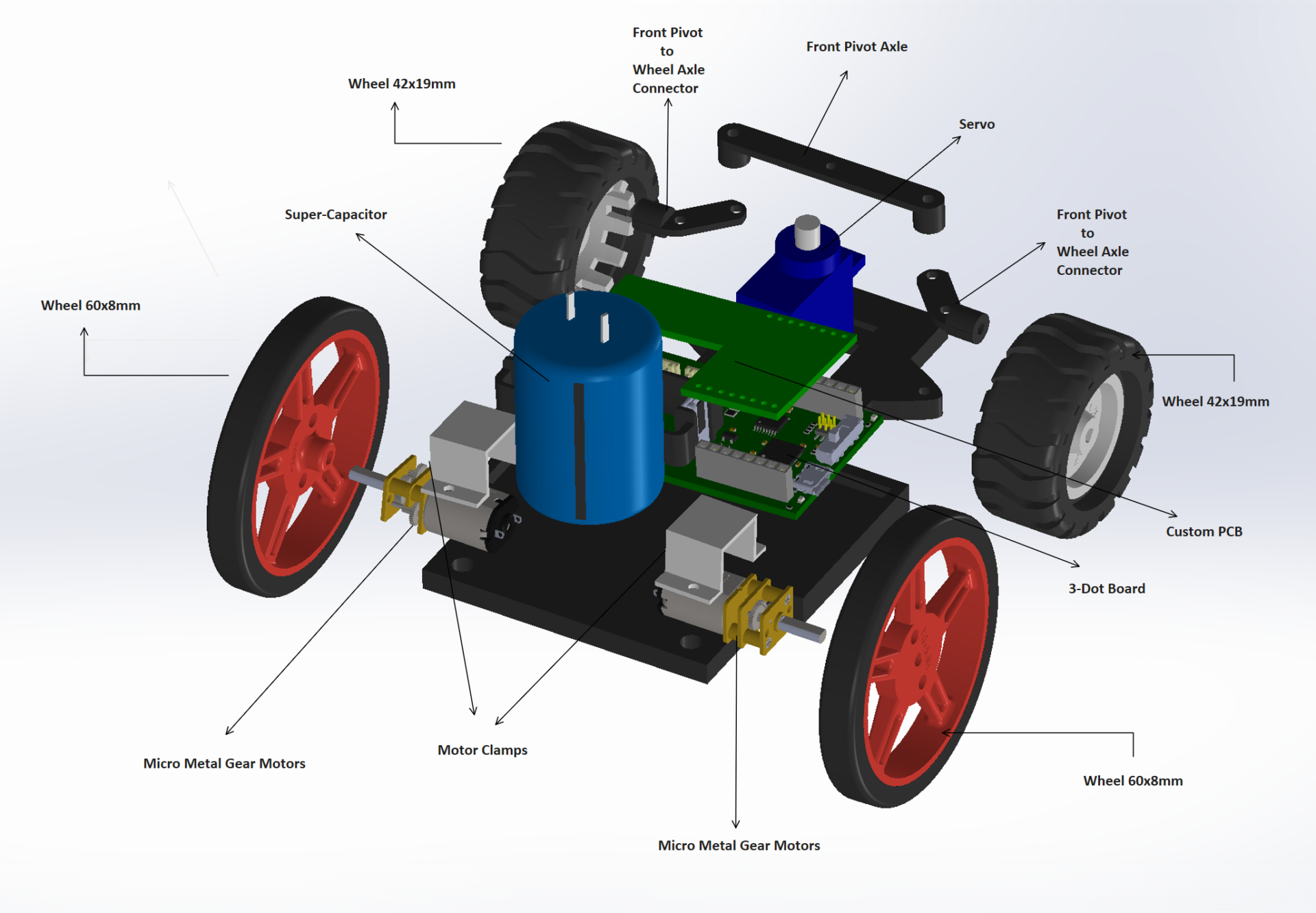
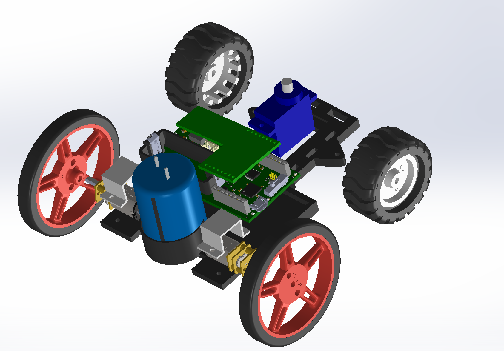
V3’s Annotated Exploded View
How I Would Improve V3’s chassis
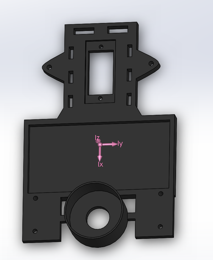
If I had the chance to improve V2/V3’s chassis it would be to create a capacitor holder and then create gaps in the chassis to reduce weight while keeping the same dimensions of our v3. Figure.14 shows just that.
Improved V3’s Mass Properties
V3’s Exploded View with New Chassis
SOLIDWORKS
How to use SOLIDWORKS
Here I will show you the basic steps of SOLIDWORKS that I believe can help you a lot if you never have used it like me before this project.
1st: You will open up SOLIDWORKS, press “Ctrl+N”, click “Part” and click “OK”.
2nd: Click “Sketch” in SOLIDWORKS as shown in Figure.17
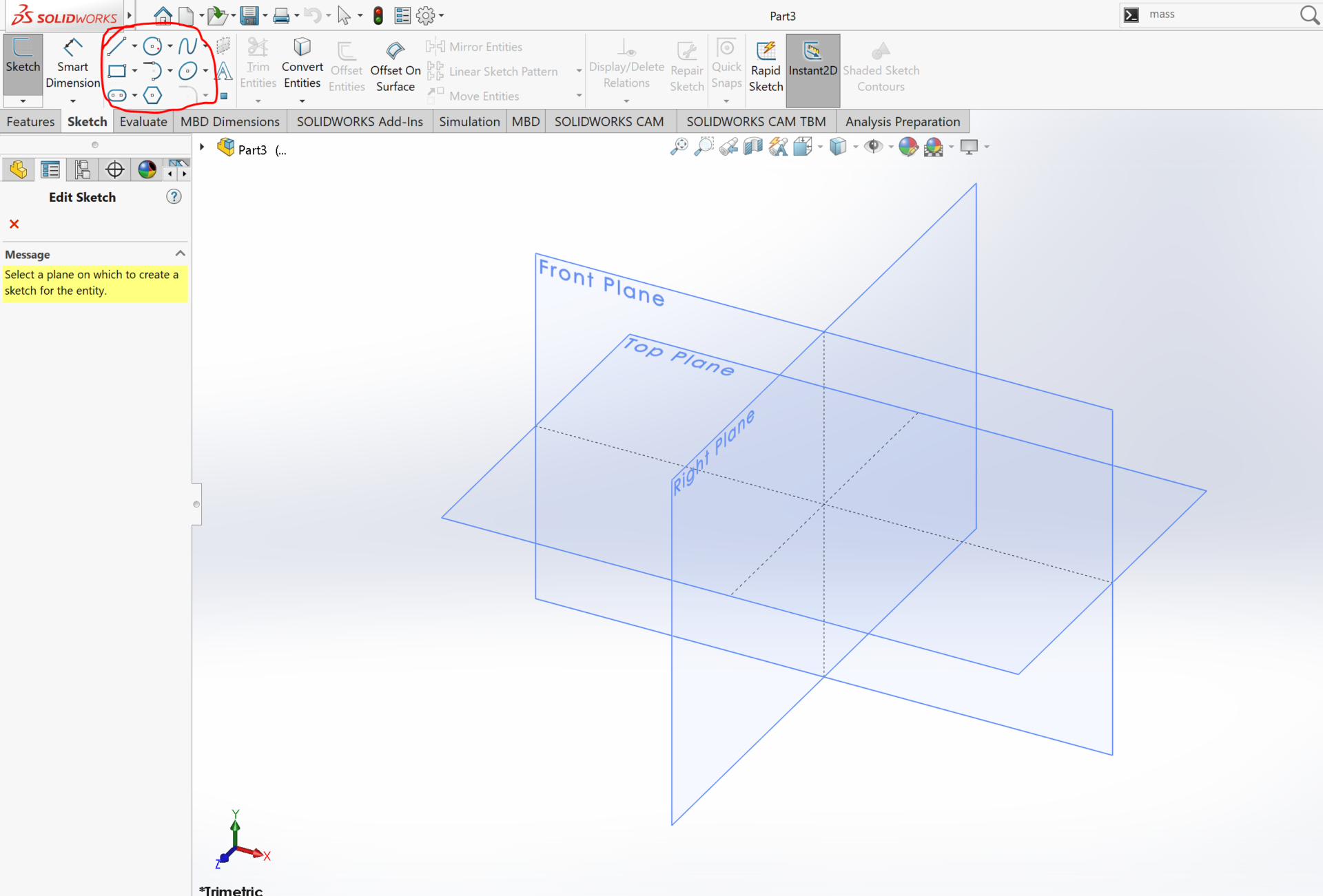
3rd: Click on any icon in red circle and then on any plane you want to work in as shown in Figure.18
4th: Create any shape. You can edit properties in the red circle to change your drawing dimensions as shown in Figure.19
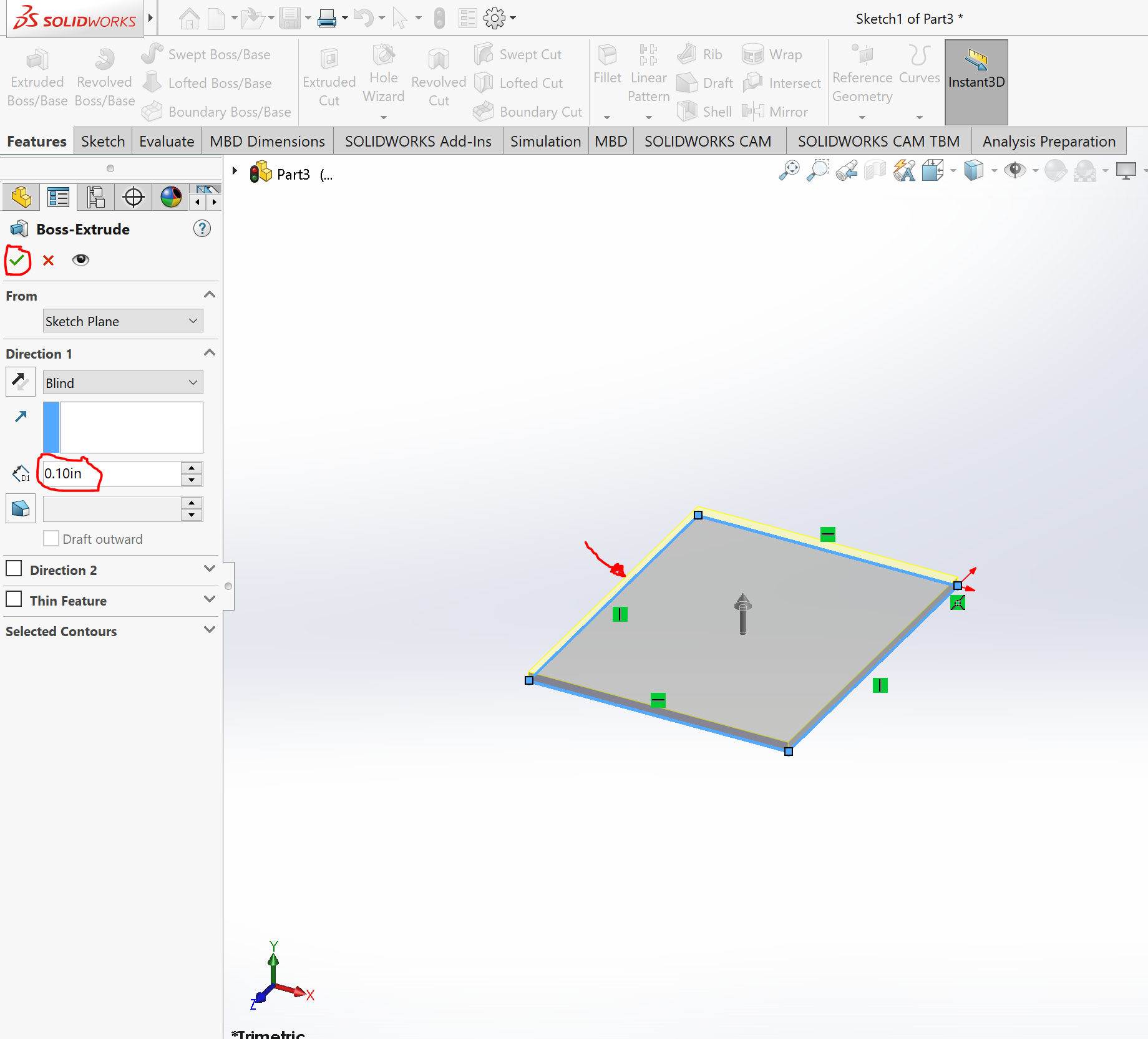
5th: Now click “Feature” on the top left followed by “Extruded Boss” right about it. Now click on the surface you created and then choose the thickness parameter you want. Lastly, click the green check symbol as shown in Figure.20
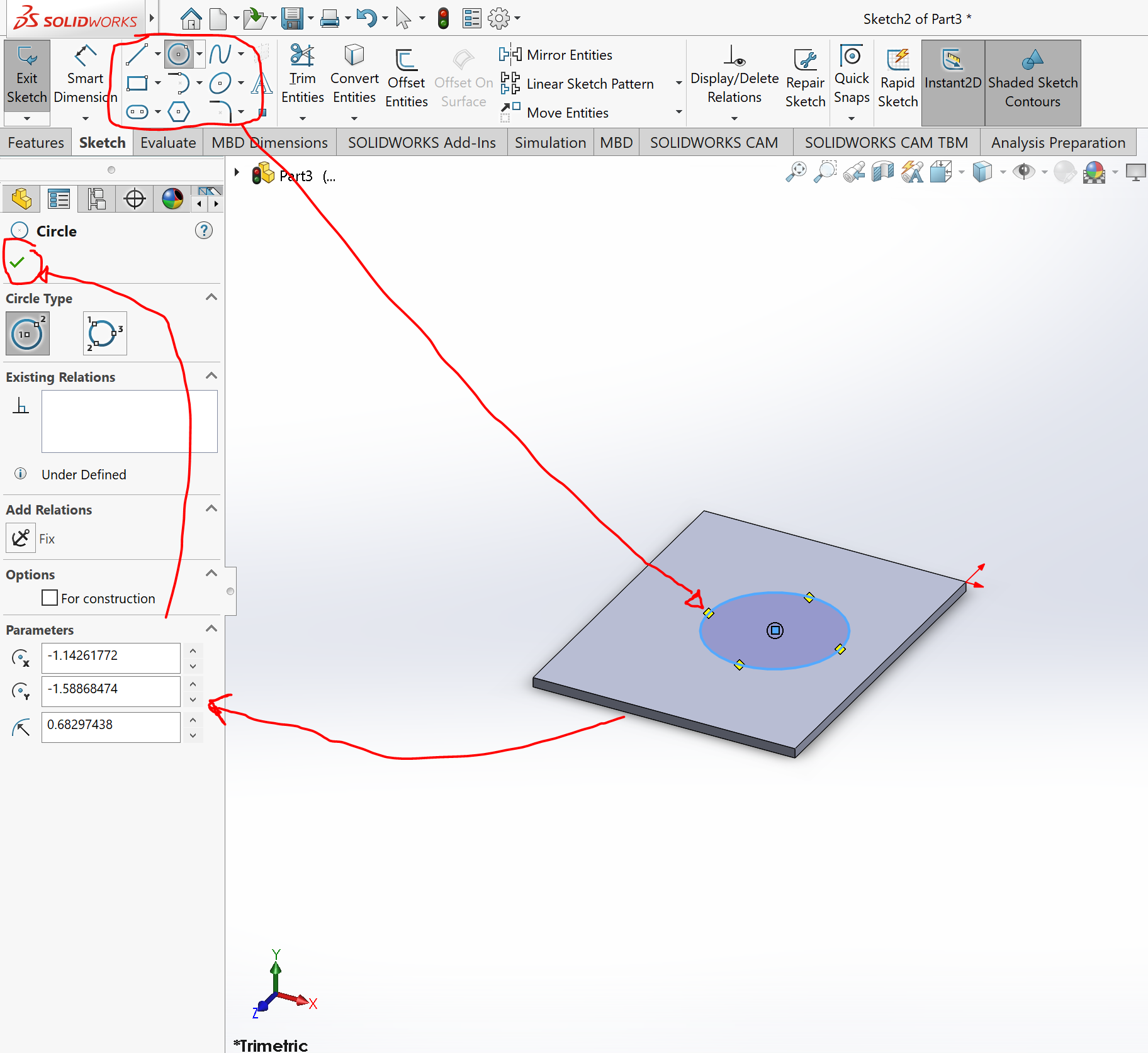
6th: Click on “Sketch” at the top left, choose an icon in the red circle you wish to replicate, click on the surface you made, change the parameters to your liking and then click the green check symbol as shown in Figure.21
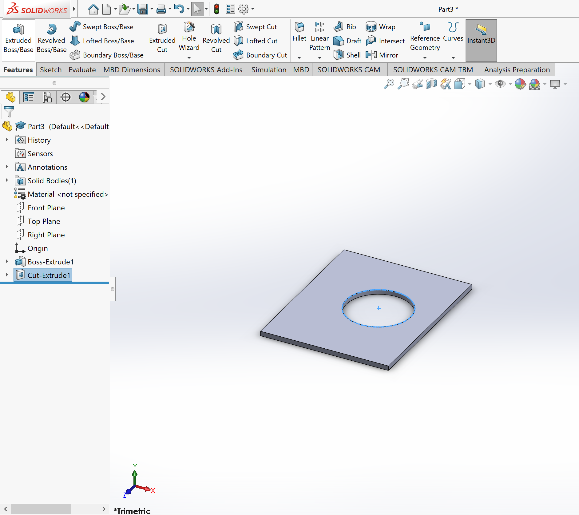
7th: Next click on “Features” at the top left, next click “Extrude Cut”, click on the shape you just made on your surface, change the parameters to your liking and click the green check symbol as shown in Figure.22
8th: Successfully extruded boss/cut as shown in Figure.23
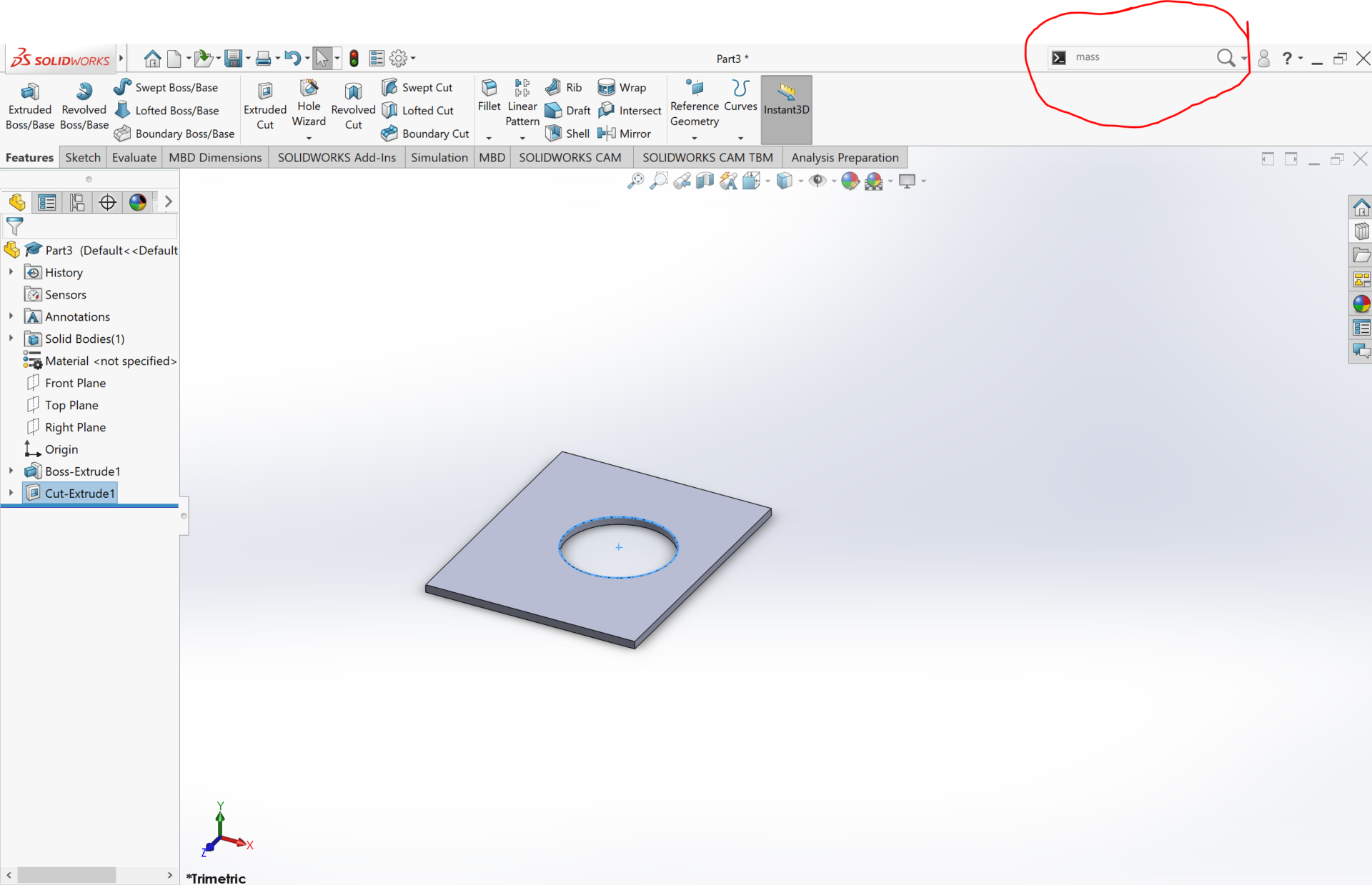
9th: If you want the “mass properties”, Center of Mass”, “Move Component”, or “Rotate Component” just type it in red circle displayed as shown in Figure.24
SOLIDWORKS Files
All SOLIDWORKS files used and created are located here…
Conclusion
Apart from yet having to see if our Mod Wheels Generation #3 accomplishes its mission of completing the loop, I had a great experience working on this project. I not learned the fundamentals regarding the engineering method but also used them for this project. This too taught me the importance of teamwork and what it’s really like out in the engineering work field. I’d like to thank Professor Hill and our T.A Christopher Hirunthanakorn for the assistance in our projects and making us understand the engineering method in a challenging, yet exciting way. This project and class has taught the true definition of engineering when comparing to other classes.
References/Resources
- https://www.dummies.com/education/science/physics/calculate-the-velocity-necessary-to-counteract-gravity-in-a-loop/
- https://www.homedepot.com/p/Everbilt-M18-2-5-Zinc-Plated-Metric-Hex-Nut-840358/204836099
- https://www.homedepot.com/b/Hardware-Fasteners-Nuts-Hex-Nuts/N-5yc1vZc2av
- https://www.homedepot.com/b/Hardware-Fasteners-Screws/N-5yc1vZc2b0?catStyle=ShowProducts&experienceName=default
- https://www.homedepot.com/b/Paint-Paint-Tools-Supplies-Tape/Double-Sided-Tape/N-5yc1vZc5dkZ1z0t5gn
- https://www.youtube.com/watch?v=v16YAUiHwt0
- https://paperlegend.com/newsletter/
- SOLIDWORKS Files

