System Mechanical Design
By: Nick Lukin (Design and Manufacturing Engineer)
Table of Contents
Introduction
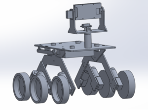
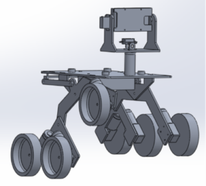
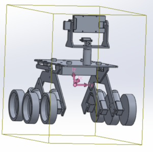
Figure 1: Overall Mechanical Design
The mechanical design of the Pathfinder utilizes many parts and sub-assemblies in order to achieve all the requirements associated with the overall design. In order to achieve the level 1 requirement of being able to successfully traverse a pre-determined course on campus it was necessary to utilize a proper suspension system. It was also necessary to completely rebuild the pan and tilt smart phone holder in order to fit a Samsung Galaxy S7 edge. The suspension design utilizes a rocker bogie suspension system very similar to the one used on the Spirit rover. Below is a description of the overall mechanical design including all of its assemblies and sub-assemblies.
Initial Design Process
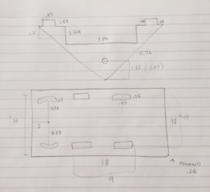
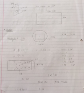
The Spring 2016 Pathfinder was used as a base reference in order to come up with a usable overall design. Each part was measured and then modeled in solidworks in order to come up with working parts and assemblies. The pictures above shows some sketches of the various parts that needed to be measured, modified and then modeled. It was necessary to change the overall geometry of the suspension and platform in order to achieve some of our desired design outcomes such as wheel clearance and lower center of gravity.
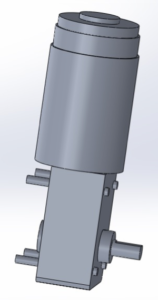
The above pictures are models of the base servo mechanism and the actual motors that are used. It was necessary to properly model these in solidworks in order to get a more accurate overall model of the pathfinder. The base servo mechanism mounts the servo that controls the pan motion of the smart phone holder. Adding the motors gives an accurate measurement of the width of the Pathfinder.
Overall Design
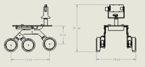
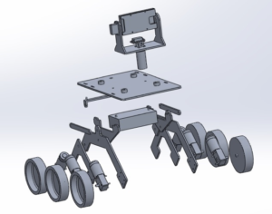
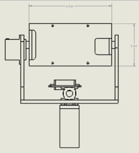
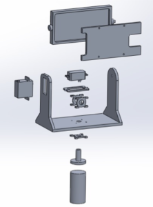
The above pictures show a 2-D drawing as well as a 3-D exploded view of the Pathfinder design. The overall dimensions of the design can be seen below.
Height: 21.6 inches
Width: 18.02 inches
Length: 23.60 inches
Floor to Top panel: 11.14 inches
The overall design can be broken into two basic sub-assemblies. These include the rocker bogie suspension system and the pan/tilt smart phone holder. Descriptions of these sub-assemblies can be seen in the next sections.
Rocker Bogie Suspension System
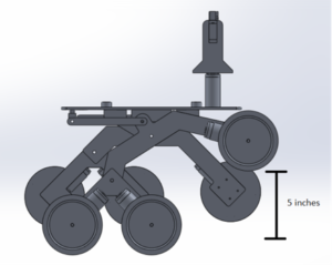
The rocker bogie suspension system that was utilized in our design is very similar to the one used on the Mars Spirit rover. This suspension system is good for uneven surfaces and requires no springs or dampening mechanisms. Each wheel can move up and down independent of one another. Another benefit of this suspension system is that the main body stays straight and upright while going up of down steep surfaces. This creates good weight distribution and helps prevent the Pathfinder from tipping over. The overall wheel clearance of the suspension system was designed to be 5 inches due to the fact that it will need to go upstairs that are about 5 inches tall. The diameter of the wheels is 6 inches, therefore the height of the Pathfinder from the ground to the bottom of the base platform is 11.14 inches.
Pan/Tilt Smartphone Holder
The pan/tilt smartphone holder is designed to hold a Samsung Galaxy S7 edge. The dimensions of the phone are 5.94 x 2.86 x 0.30 in. The holder case was designed to have the following dimensions: 6.34 x 3.26 x 0.7 in. The thickness of the case will be 0.2 inches which will allow for the phone to be fully covered. The front cover plate was designed to have cutouts in the appropriate locations. The cutouts can be seen in the picture above. These cutouts are for the camera and for the antennas in the phone. It is necessary that these do not get covered in order to obtain good signal strength. The pan/tilt servos will be able to move 180 degrees in both directions.
Lower Center of Mass
The goal of the design was to get the center of mass as low as possible. The picture above shows the center of mass in purple. The previous design had a center of mass the was above the main pivot point of the rocker bogie front arm. The design focused on lowering the center of mass below the pivot point. This was achieved by redesigning the top platform and lowing it an inch. Lowering it an inch meant that the clearance would also be 1 inch smaller which was a problem. This was solved by making the rocker bogie arms one inch longer. The electrical box and battery will also be mounted on the bottom too which helps make the center of mass lower.
Stress Test (Base platform only)
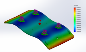
The top panel was analyzed to see how it would react to an outside force being applied to it. The top panel will carry the majority of the load which includes the Solar Panels, the Pan/Tilt Smartphone Holder, the Batteries and the Electronics. The above photo is an exaggerated simulation on how the panel may deform under certain stresses.
Solar Panel Interconnection
It will be necessary to properly interconnect the chassis to the solar panel assembly. The picture above shows the interconnection mounting points and the dimensions. 4 connection points will be used for optimal stability. These connection points will be raised pads with holes drilled through them. The solar panel assembly will then align with the holes and quick release pins win hold them in place. This will allow for quick removal of the panels.

