Posts

Prototype: Fritzing and Breadboarding – Spring 2016

Posted by: Luis Valdivia(Project Manager)
Written by: Kevin Nguyen(Electronics and Controls)


Table of Contents:

  • Introduction
  • Fritzing
  • Breadboarding
  • Protoboarding


Introduction:
It is important to prototype the schematic before sending it to the fab house. This is to ensure that the PCB would work the first time since PCB fabrication takes a lot of time and money.


Fritzing:
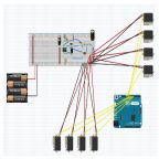
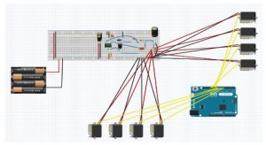
To start, a fritzing diagram is drawn on the Fritzing software. The Fritzing software allows us to draw out the connections of the physical components. This makes it easy to see where every component goes.


Fritzingfinalized

Fig 1.1 Fritzing Diagram

Breadboarding:
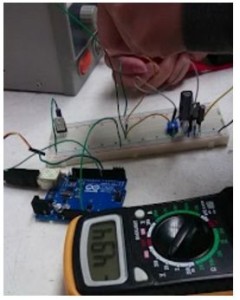
After finishing the fritzing, the circuit can be implemented onto a breadboard. Since the servo driver on our PCB does not come in through-hole packages it cannot be inserted into the breadboard. Once the buck converter is fully connected with all the supporting components, it must be tested for proper functionality. A power supply was used to test the breadboard. Setting the power supply to 14.8V to simulate the LiPo battery, we were able to acquire a 4.94V output.


testing out the buck

Fig 1.2 Testing the Buck Converter


Protoboarding:
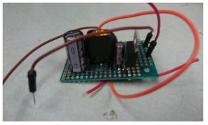
Once the circuit is verified to be working. The components are transferred onto a protoboard to make things more compact and easy to use. The protoboard could be mounted onto the quad to be used for testing while waiting for the PCB to come in.


youngbuck

Fig 1.3 Protoboard


Conclusion:
The circuit schematic must be prototyped to make sure the circuit works before sending it off to be fabricated. The prototyping process for the circuit schematic includes fritzing, breadboarding, and protoboarding. This gives the extra benefit of being able to use the prototype while waiting for the PCB. These extra steps are needed to save time and money.

UFO PCB Layout Spring 2016

Posted by: Luis Valdivia (Project Manager)
Written by: Juan Mendez (Manufacturing Engineer)

Table of contents
Introduction
Wire Traces
Building the PCB


Introduction

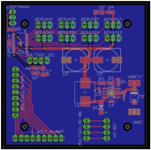
Our PCB was laid out after the schematic that was provided by our electronics and control engineer. The size of the board was set to roughly 2.5 by 2.5 inches so it can fit on the UFO frame. The screw holes were spaced out roughly 1.8 inches apart from each other. The reason this was done was to have the ability to put the multiwii on top of the pcb or vice versa. Each component was organized based on the size of the component and following recommendations from the spec sheets. Components such as the battery alarm pin headers were spaced out because alarm was approximately 3 mm thick.I isolated it from everything else so spacing would not be an issue. The servo pin headers were spaced out evenly at roughly 2 mm apart so spacing would not be an issue when being connected to the servos. The buck converter was placed close to the input voltage pads. I placed ground vias on the thermal pad of the buck converter since it was recommended by the spec sheet. Components such as the capacitors and diodes were placed next to switching output pins in order to reduce magnetic noise. The output capacitor C3 was placed as close as possible to the inductor and diode to reduce noise and to increase efficiency. Resistors “R2” and “R3” were placed close to the Feedback pin as mentioned in the data sheet. Capacitor “C1” was  placed close to the enable pin and to ground as recommended on the data sheet. The pin headers for the bluetooth connections were put in the bottom so they would not get in the way of anything else similarly to the battery alarm. Lastly the Servo driver was placed close to the servo pin headers and the lightshow pin headers were added on the top left corner of the board.


PCBFINAL

Figure 1.1 .BRD layout of PCB on Cadsoft Eagle


Wire Traces

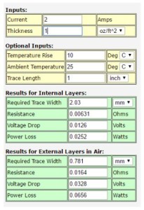
In order to make sure that mistakes were not repeated from previous semesters, we used a trace width calculator from 4PCB to calculate how thick the traces had to be. Each servo was going to be drawing a max of two amps. The board thickness was roughly 1 ounce. According to the trace calculator, the traces had to be roughly 2.03 mm thick in order to draw 2 amps. Other traces were either signal or did not draw enough current and were set to be no more than .5 mm thick.


Tracecalculator

Figure 1.2 Trace width calculator

Building the PCB

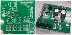
After laying out the PCB, we submitted our Layout and schematic to be ordered along with our parts list. With the help of our class president Ryland Watts, we were able to mount on the surface mounting parts using a reflow station in IEEE. We mounted on  the small resistors and capacitors first since they could have been done at once with the reflow station that we were using. Since the capacitors were bigger, we had to mount them on one at a time only because if we tried doing them all together, the heat of the reflow station would not reach the pads, therefore not mounting them properly. Once those components were on the PCB, we soldered on the pin headers. One issue we experienced was that the inductor ended up being bigger than we anticipated so the pads on the PCB were too small to mount on the inductor using the reflow station. To fix this, with the help of our electronics and control engineer, we soldered on the inductor and were able to mount on the inductor. Once the PCB was built, it was ready for testing.

pcbstogether

Figure 1.3 PCB before and after all parts have been attached

To view a video of the PCB Buck Converter stepping voltage, Click here

To view a video of the PCB Servo Power Supply, Click here

Reference:

To view the schematic for this PCB check out our blog post: PCB Design: Schematic – Spring 2016

Verification: Requirement 1.4 – Project Budget

Posted by: Luis Valdivia (Project Manager)
Written by: Anthony Becerril (Mission, Systems, and Test Engineer)


Following the Verification and Validation Matrices, this post follows the level 1 requirement 1.4 – project budget remaining below provided funds. This also satisfies its corresponding level 2 requirements if applicable.
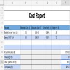
To meet the requirement, we had to finalize and approve a budget that was at most or less than the provided funding which was $167 U.S. Dollars. The budget was updated via our resource reports, specifically the project budget. A reimbursement form was created and provided receipts. This was approved by the customer and forwarded to the College of Engineering Electrical Engineering Department to finalize the process. Supporting documentation is provided below and we have completed and passed this requirement.


20160419_074842

Figure 1.1 Receipt of hobby people purchase (battery and safety bag)

paypal

Figure 1.2 Online receipt of hobbyking.com purchase (two Electric Ducted Fans)

Additional Resources:

Previous Blog Post: Verification and Validation Matrices (Spring 2016)

Verification: Requirement 1.3 – Federal Aviation Administration, Unmanned Aircraft Systems, and California State University, Long Beach College of Engineering Compliance

Posted by: Luis Valdivia (Project Manager)
Written by: Anthony Becerril (Mission, Systems, and Test Engineer)


Following the Verification and Validation Matrices, this post follows the level 1 requirement 1.3 – Federal Aviation Administration (FAA), Unmanned Aircraft Systems (UAS), and California State University, Long Beach College of Engineering (CSULB COE) compliance. This also satisfies its corresponding level 2 requirements if applicable.
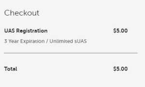
To meet the requirement, compliance of FAA, UAS, CSULB COE rules and regulations had to be done. That consisted of registering the quadcopter officially under the FAA which included a UAS registration of 5 U.S. Dollars, acknowledgment of safety guidance, and its own registration number FA3C74WXLT. Supporting documentation is provided below and we have completed and passed this requirement.

$5

Figure 1.1 Registration Fee along with expiration

requirementstofly

Figure 1.2 User must follow these safety guidelines while flying aircraft

REGISTRATION

Figure 1.3 UFO Quadcopter MUST display registration number while flying. We attached the registration number to the ducted fans.

Additional Resources:

Previous Blog Post: Verification and Validation Matrices (Spring 2016)

Bluetooth Communication: Smart Phone Applications Spring 2016

Posted by: Luis Valdivia (Project Manager)
Written by: Anthony Becerril (Mission, Systems, and Test Engineer)

Table of contents:
Introduction
EZ-GUI Ground Station
BTCon2Dron
Conclusion
Additional Resources

Introduction:

Upon setting up the new bluetooth module, the next step was researching application solutions on how to control the quadcopter with bluetooth communication. After researching, we found two android applications: EZ-GUI Ground Station and BTCon2Drone. The reason as to why we had only android applications is because when searching for applications on the apple store, there aren’t many applications that provide bluetooth communication or control for a quadcopter. A possibility as to why this is may be the difference in the process for publishing applications with apple being more strict than android therefore leading to less applications available. Also with apple being very unique and specific in its operating system, less applications are made for iPhones than for Android phones.  


EZ-GUI Ground Station
Our first application found was EZ-GUI Ground Station by Eziosoft. This application only provided us data being provided by the MultiWii board components. The data is being displayed on dashboards provided by the application main menu. One of the dashboards was premium and not accessible to use. Screenshots of the menu and dashboard are detailed below:


Click here To see an attempt at controlling the UFO quadcopter with the EZ-GUI app


BTCon2Drone
Our second application found was BTCon2Drone by PingguSoft. This application also provided data from the MultiWii board with the addition of the target feature of controlling the quadcopter. This application also has various dashboards but we focused on the controller one. With this controller we can control the quadcopter which takes us a step closer at controlling the quadcopter via bluetooth. Screenshots of the menu and dashboard are detailed below:


Click here  To see the BTCon2Drone control the UFO quadcopter


Conclusion:
Unfortunately this application has a twenty-four hour trial period with the full application costing five dollars. Another setback was during testing, the response time for controlling is slow and isn’t safe for our intentions of controlling during flight. Also when thrust gets to a high level, the bluetooth module starts to fail and disarming is no longer able to be executed. Further test and work is to be done to see if there are  ways to making this more reliable and robust for flight control. Applications are also subject to updates with changes in design and graphics or even being terminated which is why Arxterra application control is the end goal.


Additional Resources:
Previous Blog Post: Bluetooth Module Update (Spring 2016)
Previous Blog Post: Learning To Use a Bluetooth Module (Fall 2015)
Previous Blog Post: Bluetooth Interface to Arxterra Application (Spring 2015)
EZ-GUI Ground Station Application Download
BTCon2Drone Application Download

Verification and Validation Matrices Spring 2016 UFO

Posted by: Luis Valdivia (Project Manager)
Written by: Anthony Becerril (Mission, Systems, and Test Engineer)
In order to have mission success we look back to our requirements and seeing the status of meeting them. They have been updated after further discussion and meeting with the customer and their needs. The most up to date requirements are below:

Requirements:

Level 1
No. Requirement
1.1 The UFO Ab-ducted quadcopter must maintain stable flight during operation.
1.2 Project will be completed before the end of Spring 2016 semester.
1.3 Quadcopter must follow rules and regulations to ensure safety for the user(s).
1.4 Overall expenses for this project shall remain below the set budget of the customer.
1.5 Quadcopter will feature a light show with programmable user input.
1.6 The UFO Ab-ducted quadcopter will feature wireless communication for user input.
1.7 UFO Ab-ducted quadcopter will feature a durable shell to protect components.

Table 1.1 List of all Level 1 requirements for UFO Spring 2016

Level 2
No. Requirement
2.1.1 The UFO Ab-ducted quadcopter will counter the undesired Electric Ducted Fan (EDF) torque to maintain stable flight.
2.1.2 The UFO Ab-ducted quadcopter will complete the following flight course: successfully fly around a tree at the nearby park across from Whaley Park, Long Beach, California
2.3.1 The UFO Ab-ducted quadcopter will comply by the rules and regulations of the Federal Aviation Administration (FAA), Unmanned Aircraft Systems (UAS), and California State University, Long Beach’s College of Engineering (CSULB COE) flying policies.
2.4.1 Total overall expenses for the UFO Ab-ducted quadcopter project will be lower than $300.00 USD.
2.5.1 A custom lightshow will be made available through use of a NeoPixel and programmable via the Arxterra Application.
2.6.1 Wireless communication will operate using Radio Controlled (RC) communication to control the UFO Ab-ducted quadcopter’s vertical motion.
2.6.2 Wireless communication will operate using Bluetooth communication to control the UFO Ab-ducted quadcopter’s vertical motion.
2.7.1 The UFO Ab-ducted quadcopter’s protective shell will be manufactured of lexan plastic utilizing the vacuum form molding method.
2.7.2 A newly made Printed Circuit Board (PCB) will be manufactured to secure connectivity.

Table 1.2 List of all Level 2 requirements for UFO Spring 2016

These requirements are then broken down into Verification and Validation matrices. Our verification matrix follows through with all our requirements and properly tests all the work being done on the project by our team. There is a shall statement tied with a verification method to get results that lead to a pass or fail of the requirement. As for validation, this matrix is to be used during the final demonstration where the customer will assess the project status through the listed validation statements. Not including the validation matrix, all requirements in the verification matrix will also be followed up with a blog post for each listed item to details the results and conclude whether it passes or fails.
Verification Matrix:


Requirement Number(s) Shall Statement Verification Method Summary Verification Method Results Pass/Fail
1.1, 2.1.1, 2.1.2, 2.1.3 UFO Ab-ducted quadcopter shall maintain stable flight for at least 7 seconds. Quadcopter will be timed via digital stopwatch from start of flight to end of flight. Flight will also be recorded to verify flight duration. Only flights that are stable with minimal yaw rotation will be accepted. Time must be within the tolerance of +/- 0.2 seconds (time between 6.8-7.2 seconds). Test TBD TBD
1.2 Project shall be completed before end of Spring 2016 semester which ends on Friday, May 13th, 2016. Project efforts shall be completed by Friday, May 13th, 2016 therefore no more work to be done thereafter Analysis TBD TBD
1.3, 2.3.1 UFO Ab-ducted quadcopter shall comply by rules and regulations of the Federal Aviation Administration (FAA), Unmanned Aircraft Systems (UAS), and California State University, Long Beach’s College of Engineering’s flying policies. To fulfill compliance of FAA, UAS and CSULB COE, the quad copter shall be registered as a flying object and shall not break any rules and regulations Inspection quadcopter is officially registered. It was registered under the identification number FA3C74WXLT. It also abides by the rules and regulations such as: Pass
1.4 Budget for this project shall remain below provided budget of 167 U.S. Dollars Shall have approved budget with evidence via reciepts with the total cost lower than the provided budget Analysis Budget was submitted and approved at a total of $156.34 with supporting documents and information to complete the reimbursement process Pass
1.5, 2.5.1 UFO Ab-ducted quacopter shall feature a light show of at least 3 unique patterns. The lightshow shall be displayed and while on display is to give at least 3 unique patterns Inspection TBD TBD
1.6, 2.6.1, 2.6.2 The UFO Ab-ducted quadcopter shall be capable of control with wireless communication for a range of at least 10 feet. The wireless communication will be setup and tested with increasing distances away from the quadcopter being recorded Test TBD TBD
1.7, 2.7.1 The UFO Ab-ducted quadcopter’s Printed Circuit Board (PCB) shall power at least one servo at 5 five volts via a buck converter. Each pin and component on the PCB will be tested to give the 5 volts from the battery/voltage source. Test TBD TBD

Table 1.3  Verification Matrix for UFO Spring 2016


Validation Matrix:

Requirement Number Objective Validation Method Summary Validation Method Pass/Fail
1.1, 2.1.1, 2.1.2, 2.1.3 UFO Ab-ducted quadcopter shall maintain stable flight. Customer will evaluate stable flight of quadcopter. Demonstation
1.3, 2.3.1 UFO Ab-ducted quadcopter shall comply by rules and regulations of the Federal Aviation Administration (FAA), Unmanned Aircraft Systems (UAS), and California State University, Long Beach’s College of Engineering’s flying policies. Customer will observe registration number and paperwork. Inspection
1.4 Budget for this project shall remain below provided budget of 167 U.S. Dollars Customer will observe and confirm budget paperwork. Inspection
1.5, 2.5.1 UFO Ab-ducted quacopter shall feature a light show of at least 3 unique patterns. Customer will observe lightshow. Inspection
1.6, 2.6.1, 2.6.2 The UFO Ab-ducted quadcopter shall be capable of wireless communication. Customer will observe wireless communication via RC and bluetooth. Demonstation
1.7 The UFO Ab-ducted quadcopter’s PCB shall power at least one servo via buck converter. Customer will observe servo powered via PCB servo driver. Demonstation

Table 1.4 Validation Matrix for UFO Spring 2016

RC Control Spring 2016

Posted by: Luis Valdivia(Project Manager)
Written by: Kevin Nguyen(Electronics and Controls)


Table of Contents:
– Introduction
– Transmitter and Receiver
– Setting up the MultiWii
– MultiWii GUI
– Arming and Disarming


Introduction:
Being able to use the RC controller early on in this project will be very beneficial since it will make testing safer and more efficient. Since EDF’s spin at very high rpms, it is not a good idea to keep your hands on the quadcopter while testing. The RC controller will allow you to test the quadcopter at a safe distance. An added benefit to using the RC controller is that it doesn’t add that much weight to your system. All that is needed for the quad to communicate with the controller is the receiver. This blog will guide you through setting up RC control.


Transmitter and Receiver:
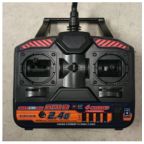
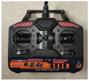
The RC controller that we used is the HK-T4A V2. This comes with a transmitter and a receiver. Most likely, you will be using the same controller as us so they would already be binded, but if not, follow this video to bind your devices. The transmitter will be from the remote controller. It will send a 2.4Ghz signal to the receiver on the MultiWii. The RC signal is much more reliable than bluetooth and is capable of transmitting at much further distances.
The transmitter controls the throttle, yaw, pitch, and roll of the quadcopter. The left joystick controls the throttle and the yaw; Vertical direction controls the throttle, horizontal direction controls the yaw. The right joystick controls the pitch and the roll; Vertical direction controls the pitch, horizontal direction controls the roll.

rc controller


Fig 1.1 RC Controller

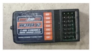
The receiver is connected to the MultiWii. Each channel on the receiver corresponds to a command on the controller. The transmitter sends out signals in the form of radio waves and the receiver converts those signals to electrical signals for the MultiWii to read. The connections on the receiver must be connected to the appropriate pins on the MultiWii in order to control it properly. Refer to this blogpost for MultiWii connections.

rc receiver

Fig 1.2 HK-T4A Receiver

Setting up the MultiWii:

To set up the MultiWii to be compatible with your quad, you need to download the MultiWii source code here. After getting the source code, go into the config.h file and select the appropriate configurations based on your project. To select an option, simply remove the comments(//).

For our project, we used:
#define QUADX
#define MINTHROTTLE 1150
#define MAXTHROTTLE 2000
#define I2C_SPEED 400000L
#define INTERNAL_I2C_PULLUPS
#define FREEIMUv035_BMP

Copy and paste this anywhere into the config.h file:
#define MAG_ORIENTATION(X, Y, Z) {magADC[ROLL] = -Y; magADC[PITCH] = X; magADC[YAW] = Z;}

Some things to mention are that the minthrottle should be kept as is. The quadcopter needs to be under a certain throttle to arm and if the minthrottle is set too high it won’t reach that arming point. Another thing is that for the board options, the MultiWii isn’t listed there, using FREEIMUv035_BMP would work as well.

MultiWii GUI:
The zip download for the source code included a GUI as well. The gui can be used to change the PID settings and calibrate the sensors. The GUI only monitors the sensors, you can’t control the device through it.

Arming and Disarming:
The most important commands for controlling the quadcopter is arming and disarming. Arming connects transmitter and receiver so that you can begin communication. Disarming disconnects the communication. If it flies out of control during testing, you can disarm to stop the motors from spinning. Typically, to arm you pull the throttle down and yaw to the right. To disarm you pull the throttle down and yaw to the left. This is convenient since you can arm and disarm with one joystick. The arming and disarming commands can be changed in the config.h file.

Works Cited:
https://www.youtube.com/watch?v=JyAyM1f_O3Q
https://www.arxterra.com/multiwii-esc-and-receiver-connections/
http://dl.btc.pl/kamami_wa/hk_27033_2.pdf


Spring 2016 re-design of structure rods

Posted by: Luis Valdivia (Project Manager)
Written by: Juan Mendez (Manufacturing Engineer)

Table of contents
Introduction
Approach
Re-design

Introduction

Space and weight was an issue with the vehicle. Since we were going to add a buck converter to control the brushless fans we had to reduce the weight of our current vehicle in order to compensate for the weight added on by the brushless fans and buck converter. We also noticed, some of the rod ends were broken from over tightening the set screws to the brackets (from previous semesters). Figure below demonstrates the damaged rods. 

Figure 1.1 Demonstration of damaged Carbon Fiber rods

20160501_135111

Approach

To reduce the weight, I redesigned the rods that were hold the ducted fans together and made them smaller in length. There were three rods that held the fans together, One of which was 6 inches long and the other two were 2.75 inches long. This was a simple modification. I made the rods to be .46 inches in diameter which was the same size as the previous rods. Since we wanted the rods to be shorter, I made them 1.7 inches long. By doing so, we were able to get rid of the long rod and have four individual rods for each ducted fan. We were able to reduce the weight from 5 grams to 3 grams. 

Re-design

Figure 1.2 Design of rod next to 3d print of rod

rodcomparison

Figure 1.3 New position of battery due to 3d printed rod

We were also able to remove the middle part of the frame which gave us more space to work with. Now we have no worries about the battery hitting the floor or any surface that the vehicle is resting on.

batterycomparison

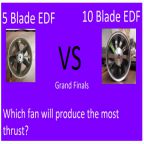
Spring 2016 Trade off study: 5 Blade EDF vs 10 Blade EDF

Written by: Luis Valdivia (Project Manager)
Posted by: Luis Valdivia (Project Manager)

Table of contents
Introduction
Results
Conclusion


Introduction:
Due to weight concerns, the spring 2016 UFO Ab-ducted group was advised [by the instructor] to perform trade off studies between 5 blade Electric Ducted Fans (EDFs) and 10 blade Electric Ducted Fans (EDFs). This study will give our group and understanding the benefit of either configuration. Ideally, the 5 blade fans would be lighter than the 10 blade fans. If we are able to deliver the same amount of thrust with a lighter fan, our vehicle would be able to achieve liftoff with the same sized EDFs.


Results:
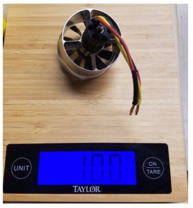
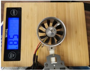
Weighing both EDFs, we measured the 5 blade EDF at 93g and the 10 blade EDF at 100g.

Figure 1.1 Weight of 5 blade EDF (in grams)

5bladeweight

Figure 1.2  Weight of 10 blade EDF (in grams)

10bladeweight

Table 1.1 results from different thrust values for 5 blades edfs and 10 blade edfs

Throttle 5 blade EDF (g) 10 blade EDF (g) Allowed weight of vehicle with 5 blades in (g) Allowed weight of vehicle with 5 blades in (g)
off 0 0 0 0
min 7 7 14 14
mid 140 235 280 470
max 530 650 1060 1300

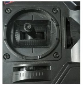
Figure 1.3 Throttle position at minimum (after multiwii has been armed)

zerothrust

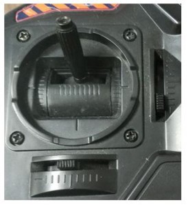
Figure 1.4 Throttle position at middle

midthrust

Figure 1.5 Throttle position at maximum

fullthrottle

Conclusion:

Measuring the thrust with the setup in figure 1.6 and figure 1.7 , we concluded the 10 blade fans produced more thrust with no significant change in weight or size to the 5 blade competitors. For our application, it seems like the 10 blade fans will bring in slightly more weight that won’t contribute to much since they produce almost twice the amount of thrust the the 5 blade fans.

Figure 1.6  Set up used to measure thrust (in grams) of 5 blades

5bladethrustweight

Figure 1.7 Set up used to measure thrust (in grams) of 10 blades

10bladethrustweight

Design(s) of 3D printed attachments Spring 2016

Posted by: Luis Valdivia (Project Manager)

Written by: Juan Mendez (Manufacturing Engineer)

Our vehicle has a yaw problem which causes it to be unstable. After brainstorming a few ideas, we have decided to attack this problem by adding on attachments in order to perform thrust vector control using servos and also be adding flaps to redirect the direction of the thrust.

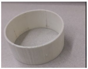
Before making our design, there were several parameters that we had to take into account such as ensuring that the attachments fit the ducted fans. For one we needed to keep the attachments as light as possible to not add on too much weight on to the vehicle however we could not for too light for several reasons. The parts that were 3D printed needed to be no less than 2 mm thick. The reason for this is because the 3D printer that we were using could not print any less than that. We first had a prototype printed to see if we could use a 3D printed part that was the thin. Once we had printed it, we saw that the part was way too thin to use and was easily broken. In order to make sure that the attachments weren’t too thin to break, we increased the thickness to 2.54mm which is roughly .1 inches thick. Once we printed a small prototype, we saw that it was much more durable than the 2mm one and we were able to easily drill through it without breaking as seen in Figure 1. 

Figure 1  3D printed duct attachment 
duct ring

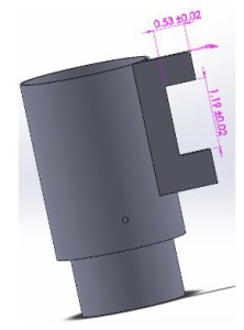
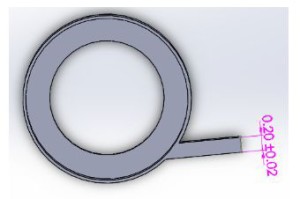
The next minor challenge that I had to consider was being able to mount on servos to the attachments. The servos were measured to have a height of 1.18 inches and needed to be mounted on to the cylindrical shape. We were initially going to make brackets and screw them in to lock the servos in place however it would be a challenge since we did not have a flat surface and we did not know if adding on screws into the attachment would affect the air flow. After consulting with my project manager, he suggested extruding a thin block out of the attachments and then mounting them onto their. I went with this suggestion and properly dimensioned the extrusion to fit the servo. Initially I designed the extrusion block to be roughly 1x .2x 2.25 inches in size. From there I made an inner cut that was .53x 1.19 inches so the servo can easily fit in (Figure 2). I had these printed and checked to see if both servo EDF could fit on to the attachment. Sure enough both did. In order to secure the servo, I had to drill into the extruded block. For this reason I made the block .2 inches thick, so it would not break off when drilling (Figure 3). Once making the holes, the servo was easily mounted on to the attachments.

Figure 2 CAD of thrust vector chamber with servo flaps (side view)
side view of chamber

Figure 3 CAD of thrust vector chamber with servo flaps (top view)
top view of chamber

        Next we had to make sure that these attachments fit into our Electric Ducted fans. The ducted fans that we were using have an outer diameter of 53mm. I dimensioned the attachments to be slightly bigger than this in order for it to be able to slip on to the EDF. In order to not waste material and time, I had only one attachment be printed. Sure enough it did not fit and was way too tight to even slip on without damaging the attachment. I made designed the attachments to have roughly an inner diameter of 54.1mm which was approximately 2.13 inches (Figure 4) with an outer diameter of 2.23mm (Figure 5). Once making the adjustments, we were able to slip on the prototype into the EDF.

Figure 4  CAD of thrust vector chamber demonstrating inner diameter
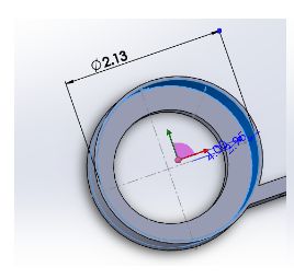
idkwhatthisis      

Figure 5  CAD of thrust vector chamber demonstrating outer diameter
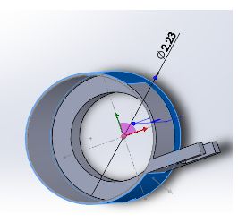
idkwhatthisis2

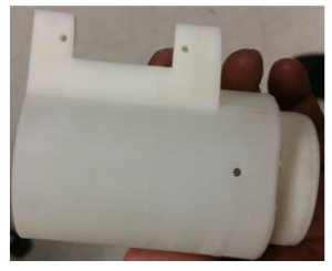
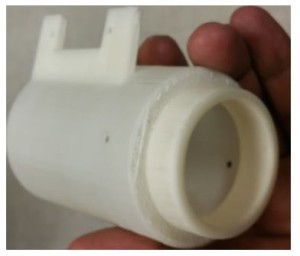
        Since we were going into thrust vectoring, I needed to make sure that the servos could move the attachments without causing any problems. One of the issues I noticed when designing the attachments was that after it rotating roughly 45 degrees, there was going to be a gap that would make air leak out, which could cause an addition issue when trying to stabilize the vehicle. To fix this problem, I made an inner cylinder to close off the gap and made it to have an outer diameter of 1.75 inches (Figure 6) and a length of 1 inch (Figure 7). Because of this, when the middle attachment rotated, there was no gap to leak air. The fabricated part can be shown in Figure 8A & B.

Figure 6 CAD of thrust vector chamber demonstrating inner diameter (second level)
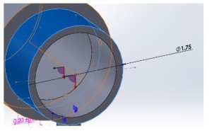
idkwhatthisis3

Figure 7 CAD of thrust vector chamber demonstrating outer diameter (second level)
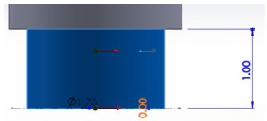
idkwhatthisis4

Figure 8A 3D Printed thrust vector chamber (side view)
idkwhatthisis5

Figure 8B 3D Printed thrust vector chamber (alternate view)
idkwhatthisis6

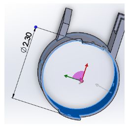
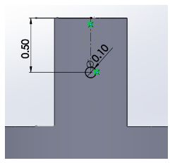
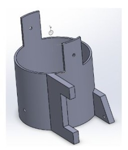
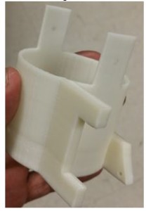
        Next was to design the middle attachment. The middle attachment was a much simpler design since much was learned from making the top one. This one just needed to have an inner diameter that was slightly bigger than the top one so it can fit and move. In order to give it a bit more space to move, this attachment had in inner diameter of 2.3 inches (Figure 9). In order to mount on this attachment to the top one, I made the mounts to be roughly 1 inch tall to compensate for the inch clearance that was given from the top attachment. I made a pilot hole on this that is in the center of the mount which was roughly .5 inches from the top of the attachment (Figure 10). An extrude block was added on to this attachment as the previous one, however an additional extrude block was added on in the back in order to have the servo joint attached on to it (Figure 11). There, the top servo was going to push and pull on to this attachment. Ideally this part was not meant to be this long, however we needed to give enough space for the servo. To control the bottom attachment. The fabricated part can be shown in Figure 12.

Figure 9 CAD of thrust vector chamber demonstrating inner diameter
idkwhatthisis7

Figure 10 CAD of thrust vector chamber attachments
idkwhatthisis8

Figure 11 CAD of thrust vector chamber (second level)
idkwhatthisis9

Figure 12 3D Printed thrust vector chamber
idkwhatthisis10

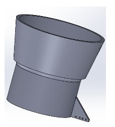
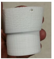
        Lastly we needed to make the bottom attachment. This was the simplest design since it was a funnel shape. In height, the funnel ended up being roughly two inches. As before, an extruded block was added on to this but just to connect to the servo, not to mount on (Figure 13). The fabricated part can be shown in Figure 14.

Figure 13 CAD of thrust vector chamber (lowest level)
idkwhatthisis11

Figure 14 3D printed thrust vector chamber (lowest level)
idkwhatthisis12

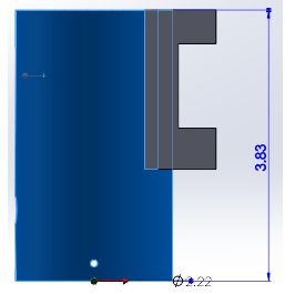
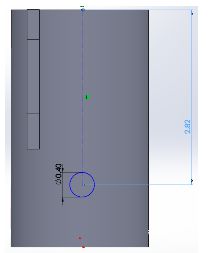
                Our second design was to control the yaw by adding flaps to counter the direction of the thrust. For this design, the top part was relatively similar to the previous one except it this not have an additional cylinder to close off any air gap. Also the height was made slightly smaller for the same reason of not having to worry about the air gap. The height of this attachment was roughly 3.83 inches with the same thickness and diameters of the previous design (Figure 15). The reason for this height again was because the EDF height including the coils was roughly 2.82 inches so I needed to make sure that there was a hole big enough to fit in the wires to power it on (Figure 16). In order to make this hole big enough, I needed to make sure there was enough space to make it. Also I needed to make sure that the flaps had enough space to mount on to the attachment.


Figure 15 CAD of thrust vector chamber demonstrating dimensions
idkwhatthisis13

Figure 16 CAD of thrust vector chamber with inner diameter
idkwhatthisis14

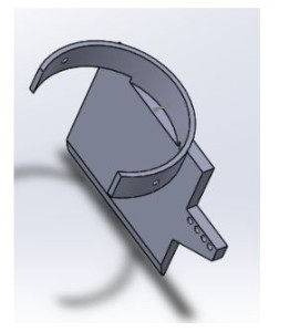
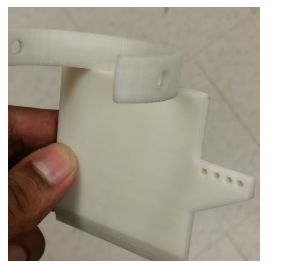
        There was much thought put into making the flaps to control the direction of the thrust. Initially the idea was to have the flaps go inside and the servo would rotate it however the problem with this was that it could not go in the middle of the attachment. The reason for this is because as the flap turned, there would be a big gap which would leak air out in a direction which would not be in our control. To attempt to solve this, we thought of making the top part of the flap bigger to block off the air gap. The problem with is now was that the top part was going to easily hit the attachment and would not let the flap rotate the way it should. The third idea was had was to remove the flap from being in the middle and putting it in the inner corner of the attachment. This did not work simply because the flap would not be able to rotate without hitting the attachment. After thinking it over with the project manager, we decided to mount on the flap outside of the attachment. I designed the flap to be able to mount on to the cylindrical attachment by making it the same shape. Some parts were trimmed off in order for it to not scrape when moving. The flap itself was designed as a prototype. It was made wide enough to cover the thrust of the EDF and long enough to redirect the thrust. The flap was made .2 inches thick in order to make it durable and hard to break as the EDF was going to be pushing against it. Similarly to the previous designs, and extruded part was added on simply to be able to attach the servo joint to push and pull the flap. The model and fabricated part can be seen in Figure 17A & B.

Figure 17A CAD of thrust vector flap
idkwhatthisis15

Figure 17B 3D printed thrust vector flap
idkwhatthisis16


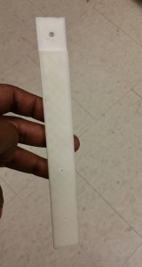
Lastly we noticed that if we were going to use all these attachments then we were going to have a problem with the legs since the attachments were long and were going to hit the floor. I modeled out new legs which were long enough so the attachments wouldn’t hit the ground when standing. These legs were approximately 7.25 inches long total but was given one inch clearance to mount them on to the vehicle (Figure 18). They were designed to be .2 inches thick so they would not break easily since it was supporting the weight of the vehicle. The fabricated part can be seen in Figure 19.

Figure 19 CAD of replacement legs                                  
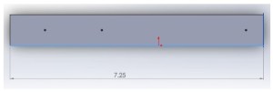
idkwhatthisis17

Figure 19 3D printed replacement leg

leg

Though these attachments have been modeled and fabricated, we were not able to use any of them nor the servos simply because the added too much weight to the vehicle and made it too heavy to fly. Even adding on the servos alone made the vehicle too have so we could not use those however these concepts can be used for future semesters if they choose to go with a similar approach and taking account the weight ahead of time.