UFO Light show setup
Posted by: Luis Valdivia (Project manager)
By: Anthony Becerril (Mission, Systems, and Test Engineer)
Table of contents:
Intro
Step 1: Hardware via Circuit
Step 2: Software via Arduino integration
Additional Resources
Intro:
This UFO Quadcopter post is in regards to the custom light show that is created through use of a 24 LED Adafruit NeoPixel Ring and follows along previous light show posts. The following will break down the proper setup for hardware and software and additional resources available.
Step 1: Hardware via Circuit
The first step consists of setting up the appropriate circuit to properly power the ring. The following setup is emulated via breadboard although it is to be implemented onto the Printed Circuit Board (PCB) for efficiency and optimal space on the quadcopter. Protection of the ring is important for the lifetime of the LEDs. As stated by the Adafruit NeoPixel Best Practices, The following should be followed:
- 1000 microfarads capacitor should be added in parallels to power and ground terminals
- 300-500 ohm resistor between arduino data output to neopixel data input
- Minimize distance between arduino and ring
- Avoid connect ring to a live circuit. If necessary, connect ground first, then power, then data. Disconnect in reverse order.
Other practices are listed along with more details on powering, library installation, and more. The link should be thoroughly explored before moving forward. The ones listed are important for this specific setup mainly due to the high voltage battery and making sure the appropriate precautions are taken. Figure 1-1 (below) gives an overview of our circuit used.
Figure 1-1 (Fritzing diagram)
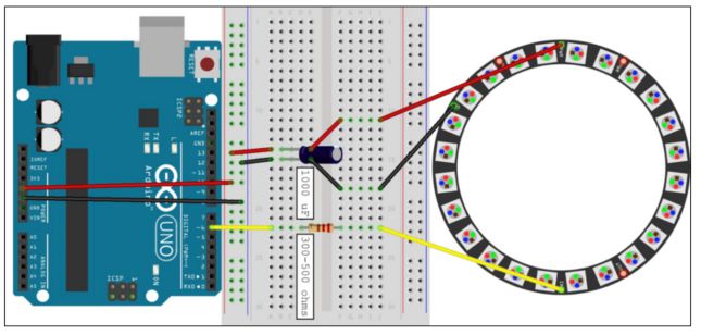
We only used 3 terminals of the ring: one power, one ground, and one data. The power supply for the emulation is a 5 volts power supply whereas when using the PCB we will be implementing such components to step down the LiPo battery used to power the quadcopter.
Step 2: Software via Arduino Integration
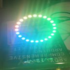
After completing the hardware, software comes next through use of the Arduino IDE. Following the Arduino Library installation, the Arduino software is now able to test the ring with the “strandtest” example code to result as follows:
From all this, the possibilities of different lights show are many when considering the many different patterns available. Next steps are creating a code to be operational via bluetooth then having successful Arxterra application control for a custom light show settings.
Additional Resources:
Previous Blog Post: How to Light Show (Spring 2015)
Previous Blog Post: Creating Neopixel Ring Light Show (Fall 2015)
Adafruit NeoPixel Ring – 24 x 5050 RGB LED with Integrated Drivers