[av_image src=’/wp-content/uploads/2017/05/HandFinal-1-300×203.png’ attachment=’25642′ attachment_size=’medium’ align=’center’ styling=” hover=” link=” target=” caption=” font_size=” appearance=” overlay_opacity=’0.4′ overlay_color=’#000000′ overlay_text_color=’#ffffff’ animation=’no-animation’][/av_image]
[av_heading tag=’h3′ padding=’10’ heading=’Spring 2017 Prosthetic Hand: Final Document’ color=” style=’blockquote classic-quote’ custom_font=” size=’24’ subheading_active=’subheading_below’ subheading_size=’15’ custom_class=”]
The Robot Company | CEO Professor Gary Hill
[/av_heading]
[av_textblock size=” font_color=” color=”]
Blog Post Created by Project Manager | Bianca Esquivel
Mission, Systems, and Test Engineer | Chris Bautista Electronics and Control Engineer | Forest Nutter
Design and Manufacturing Engineer | David Mendoza
[/av_textblock]
[av_heading tag=’h1′ padding=’10’ heading=’Executive Summary’ color=” style=’blockquote modern-quote’ custom_font=” size=’20’ subheading_active=’subheading_below’ subheading_size=’15’ custom_class=”]
By Project Manager | Bianca Esquivel
[/av_heading]
[av_icon_box position=’left’ boxed=” icon=’ue81f’ font=’entypo-fontello’ title=’Project Objective’ link=” linktarget=” linkelement=” font_color=” custom_title=” custom_content=” color=” custom_bg=” custom_font=” custom_border=”]
There are 3 main project objectives that address the problem of the customer being born without a right hand and cater to his preferred recreational activities:
Being able to operate a computer mouse, specifically being able to right click and left click.
- Ability to scroll is a plus.
Being able to pick up and drink a cup of water.
- Ability to pick up thin/fragile paper cup is a plus.
Being able to pick up and eat a chips ahoy cookie without breaking the cookie.
- Ability to pick up and eat a sun-chip without breaking the chip is a plus.
[/av_icon_box]
[av_icon_box position=’left’ boxed=” icon=’ue84c’ font=’entypo-fontello’ title=’Mission Profile’ link=” linktarget=” linkelement=” font_color=” custom_title=” custom_content=” color=” custom_bg=” custom_font=” custom_border=”]
Mission Profile from Start to Finish:
- Customer will sit down at a desk in front of a computer with a cup of water and a plate of cookies within the reach of his prosthetic hand
- The computer will have a game of minesweeper ready to play
- With the prosthetic hand he will be able to operate the mouse to play minesweeper and reset the game if he should lose or restart the game should he win
- He will be able to grasp the cup of water within his reach to drink from at his leisure without crushing the cup
- He will be able to rotate his wrist and grasp a chips ahoy cookie within his reach and eat one at a time at his leisure without crushing the cookie
[/av_icon_box]
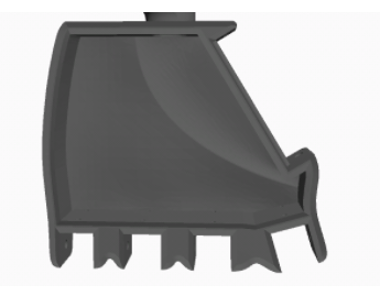
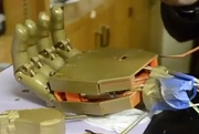
[av_icon_box position=’left’ boxed=” icon=’ue836′ font=’entypo-fontello’ title=’The Design’ link=” linktarget=” linkelement=” font_color=” custom_title=” custom_content=” color=” custom_bg=” custom_font=” custom_border=”]
- Complements the measurements of the customer
- No force sensors are included in the thumb therefore, it isn’t included in the picture
- Tips of the fingers are equipped with force sensors and rubber tips to help with gripping objects
[/av_icon_box]
[av_icon_box position=’left’ boxed=” icon=’ue811′ font=’entypo-fontello’ title=’Project Features’ link=” linktarget=” linkelement=” font_color=” custom_title=” custom_content=” color=” custom_bg=” custom_font=” custom_border=”]
- Rubber fingertips for better gripping capabilities
- Force Sensors for a more controlled grip
- Flex Sensors used to control the grip with the use of the toes
- PLA Material due to project budget
[/av_icon_box]
[av_heading tag=’h1′ padding=’10’ heading=’System Design’ color=” style=’blockquote modern-quote’ custom_font=” size=’20’ subheading_active=’subheading_below’ subheading_size=’15’ custom_class=”]
By Mission, Systems, and Test Engineer | Chris Bautista
[/av_heading]
[av_icon_box position=’left’ boxed=” icon=’ue820′ font=’entypo-fontello’ title=’System Interface’ link=” linktarget=” linkelement=” font_color=” custom_title=” custom_content=” color=” custom_bg=” custom_font=” custom_border=”]
Link to Interface Definitions:
Prosthetic Hand Interface Definitions
[/av_icon_box]
[av_toggle_container initial=’0′ mode=’accordion’ sort=”]
[av_toggle title=’System Block Diagram’ tags=”]

[/av_toggle]
[/av_toggle_container]
[av_hr class=’invisible’ height=’20’ shadow=’no-shadow’ position=’center’ custom_border=’av-border-thin’ custom_width=’50px’ custom_border_color=” custom_margin_top=’30px’ custom_margin_bottom=’30px’ icon_select=’yes’ custom_icon_color=” icon=’ue808′ font=’entypo-fontello’]
[av_tab_container position=’top_tab’ boxed=’border_tabs’ initial=’1′]
[av_tab title=’Software Block Diagram – Foot’ icon_select=’yes’ icon=’ue8bd’ font=’entypo-fontello’]


[/av_tab]
[av_tab title=’Software Block Diagmram – Hand’ icon_select=’yes’ icon=’ue8be’ font=’entypo-fontello’]


[/av_tab]
[/av_tab_container]
[av_hr class=’invisible’ height=’20’ shadow=’no-shadow’ position=’center’ custom_border=’av-border-thin’ custom_width=’50px’ custom_border_color=” custom_margin_top=’30px’ custom_margin_bottom=’30px’ icon_select=’yes’ custom_icon_color=” icon=’ue808′ font=’entypo-fontello’]
[av_heading tag=’h1′ padding=’10’ heading=’Electronics Design’ color=” style=’blockquote modern-quote’ custom_font=” size=’20’ subheading_active=’subheading_below’ subheading_size=’15’ custom_class=”]
by Electronics and Control Engineer | Forest Nutter
[/av_heading]
[av_icon_box position=’left’ boxed=” icon=’ue856′ font=’entypo-fontello’ title=’Electronics Custom Parts’ link=” linktarget=” linkelement=” font_color=” custom_title=” custom_content=” color=” custom_bg=” custom_font=” custom_border=”]
TB6612FNG
Motor Driver Requirements Needed
- 11v input
- 5v logic
- H-bridge included
- 0.15A output current
Reason for specified IC
- SMD available
- Break out board sold from sparkfun for testing
- Available on DigiKey
Link to requirements
- L1-2 Motion
- The prosthetic hand shall have individual motion in at least 2 fingers
- L2-3 Motors
- The hand should flex and extend using motors.
Arduino Micro
Purpose
- Receive and send data from the xbee
- Read Analog voltages from the force resistors
- Control the motor drivers based on inputs from the xbee
- Control the servo based on inputs from the xbee
Reason for specified MCU
- Serial Communication
- 6 Analog Pins
- 6 Digital Pins
- 4 PWM Pins
- 1 Timer
- 5v logic, but also accepts 3.3v logic
- Useful because xbee is a 3.3v device
- Available from last semester
[/av_icon_box]
[av_tab_container position=’top_tab’ boxed=’border_tabs’ initial=’1′]
[av_tab title=’Motor Driver Used’ icon_select=’yes’ icon=’ue856′ font=’entypo-fontello’]

[/av_tab]
[av_tab title=’Arduino Micro’ icon_select=’yes’ icon=’ue856′ font=’entypo-fontello’]

[/av_tab]
[/av_tab_container]
[av_hr class=’invisible’ height=’20’ shadow=’no-shadow’ position=’center’ custom_border=’av-border-thin’ custom_width=’50px’ custom_border_color=” custom_margin_top=’30px’ custom_margin_bottom=’30px’ icon_select=’yes’ custom_icon_color=” icon=’ue808′ font=’entypo-fontello’]
[av_toggle_container initial=’0′ mode=’accordion’ sort=”]
[av_toggle title=’Firmware: Foot PCB Code’ tags=”]


[/av_toggle]
[av_toggle title=’Firmware: Hand PCB Code’ tags=”]


[/av_toggle]
[av_toggle title=’Mode Chooser Flow Chart’ tags=”]

[/av_toggle]
[av_toggle title=’Motor Control Flow Chart’ tags=”]

[/av_toggle]
[av_toggle title=’Servo Positioning Flow Chart’ tags=”]

[/av_toggle]
[av_toggle title=’Xbee Flow Chart’ tags=”]

[/av_toggle]
[/av_toggle_container]
[av_hr class=’invisible’ height=’20’ shadow=’no-shadow’ position=’center’ custom_border=’av-border-thin’ custom_width=’50px’ custom_border_color=” custom_margin_top=’30px’ custom_margin_bottom=’30px’ icon_select=’yes’ custom_icon_color=” icon=’ue808′ font=’entypo-fontello’]
[av_tab_container position=’top_tab’ boxed=’border_tabs’ initial=’1′]
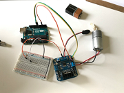
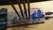
[av_tab title=’Breadboarded Xbee Circuit’ icon_select=’yes’ icon=’ue839′ font=’entypo-fontello’]

[/av_tab]
[av_tab title=’Breadboarded Flex Sensor Circuit’ icon_select=’yes’ icon=’ue8ad’ font=’entypo-fontello’]

[/av_tab]
[/av_tab_container]
[av_hr class=’invisible’ height=’20’ shadow=’no-shadow’ position=’center’ custom_border=’av-border-thin’ custom_width=’50px’ custom_border_color=” custom_margin_top=’30px’ custom_margin_bottom=’30px’ icon_select=’yes’ custom_icon_color=” icon=’ue808′ font=’entypo-fontello’]
[av_tab_container position=’top_tab’ boxed=’border_tabs’ initial=’1′]
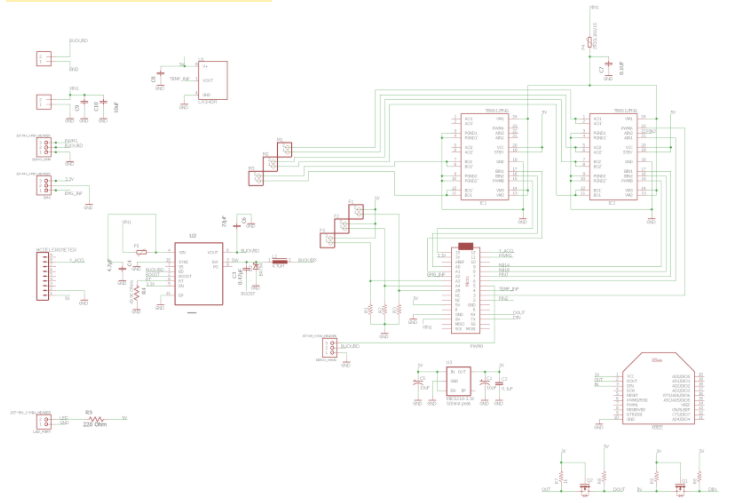
[av_tab title=’Hand PCB Schematic’ icon_select=’yes’ icon=’ue814′ font=’entypo-fontello’]

[/av_tab]
[av_tab title=’Foot PCB Schematic’ icon_select=’yes’ icon=’ue815′ font=’entypo-fontello’]

[/av_tab]
[/av_tab_container]
[av_hr class=’invisible’ height=’20’ shadow=’no-shadow’ position=’center’ custom_border=’av-border-thin’ custom_width=’50px’ custom_border_color=” custom_margin_top=’30px’ custom_margin_bottom=’30px’ icon_select=’yes’ custom_icon_color=” icon=’ue808′ font=’entypo-fontello’]
[av_tab_container position=’top_tab’ boxed=’border_tabs’ initial=’1′]
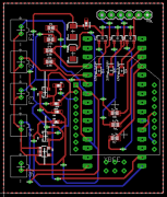
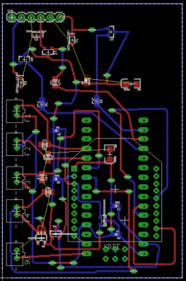
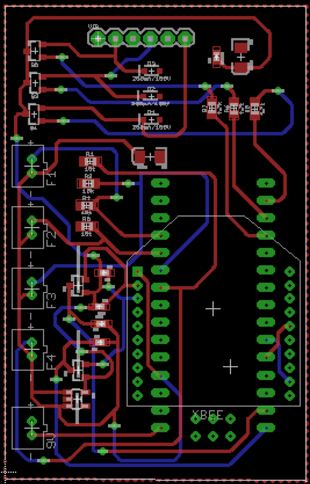
[av_tab title=’Hand and Arm PCB Layout’ icon_select=’yes’ icon=’ue814′ font=’entypo-fontello’]

[/av_tab]
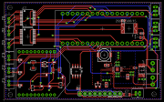
[av_tab title=’Foot PCB Layout’ icon_select=’yes’ icon=’ue815′ font=’entypo-fontello’]

[/av_tab]
[/av_tab_container]
[av_hr class=’invisible’ height=’20’ shadow=’no-shadow’ position=’center’ custom_border=’av-border-thin’ custom_width=’50px’ custom_border_color=” custom_margin_top=’30px’ custom_margin_bottom=’30px’ icon_select=’yes’ custom_icon_color=” icon=’ue808′ font=’entypo-fontello’]
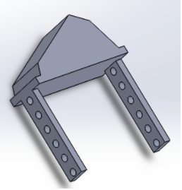
[av_heading tag=’h1′ padding=’10’ heading=’Hardware Design’ color=” style=’blockquote modern-quote’ custom_font=” size=’20’ subheading_active=’subheading_below’ subheading_size=’15’ custom_class=”]
by Manufacturing and Design Engineer | David Mendoza
[/av_heading]
[av_textblock size=” font_color=” color=”]
Link to Final Prosthetic Hand Palm Design Blog Post:
Link to Final Prosthetic Hand Fingers Design Blog Post:
Prosthetic Hand Fingers Design
[/av_textblock]
[av_icon_box position=’left’ boxed=” icon=’ue808′ font=’entypo-fontello’ title=’Verification Tests’ link=” linktarget=” linkelement=” font_color=” custom_title=” custom_content=” color=” custom_bg=” custom_font=” custom_border=”]
by Mission, Systems, and Test Engineer | Chris Bautista
Link to Verification & Validation Report – Prosthetic Hand:
V&V Prosthetic Hand
[/av_icon_box]
[av_heading tag=’h1′ padding=’10’ heading=’System Resource Reports’ color=” style=’blockquote modern-quote’ custom_font=” size=’20’ subheading_active=’subheading_below’ subheading_size=’15’ custom_class=”]
by Mission, Systems, and Test Engineer | Chris Bautista
[/av_heading]
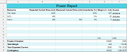
[av_icon_box position=’left’ boxed=” icon=’ue8a9′ font=’entypo-fontello’ title=’Power Allocation’ link=” linktarget=” linkelement=” font_color=” custom_title=” custom_content=” color=” custom_bg=” custom_font=” custom_border=”]

[/av_icon_box]
[av_icon_box position=’left’ boxed=” icon=’ue8d3′ font=’entypo-fontello’ title=’Mass Allocation’ link=” linktarget=” linkelement=” font_color=” custom_title=” custom_content=” color=” custom_bg=” custom_font=” custom_border=”]

[/av_icon_box]
[av_icon_box position=’left’ boxed=” icon=’ue814′ font=’entypo-fontello’ title=’Cost Allocation’ link=” linktarget=” linkelement=” font_color=” custom_title=” custom_content=” color=” custom_bg=” custom_font=” custom_border=”]

[/av_icon_box]
[av_icon_box position=’left’ boxed=” icon=’ue8c5′ font=’entypo-fontello’ title=’Burndown’ link=” linktarget=” linkelement=” font_color=” custom_title=” custom_content=” color=” custom_bg=” custom_font=” custom_border=”]
by Project Manager | Bianca Esquivel

[/av_icon_box]
[av_heading heading=’Project Resources’ tag=’h1′ style=’blockquote modern-quote’ size=’20’ subheading_active=” subheading_size=’15’ padding=’10’ color=” custom_font=”][/av_heading]
[av_textblock size=” font_color=” color=”]
Project Video: Prosthetic Limb 2017 Project Video
CDR PowerPoint: Prosthetic Hand CDR PPT
PDR PowerPoint: Prosthetic Hand PDR PPT
Project Libre & Excel Burndown: Prosthetic Limb Schedule & Burndown
Verification & Validation Report: V&V Prosthetic Hand
Solidworks Files: Mechanical Blog Post 1, Mechanical Blog Post 2
Fritzing Files: Electrical Blog Post 1, Electrical Blog Post 2, Electrical Blog Post 3
Eagle CAD Files: Electrical Blog Post 4
Arduino Code: Software Blog Post
Bill of Materials: Prosthetic Hand Reimbursement Form
The Entire 400D Prosthetic Limb Folder: Prosthetic Limb 2017 Group Folder
[/av_textblock]