Posts

Design(s) of 3D printed attachments Spring 2016

Posted by: Luis Valdivia (Project Manager)

Written by: Juan Mendez (Manufacturing Engineer)

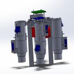
Our vehicle has a yaw problem which causes it to be unstable. After brainstorming a few ideas, we have decided to attack this problem by adding on attachments in order to perform thrust vector control using servos and also be adding flaps to redirect the direction of the thrust.

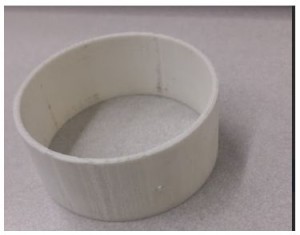
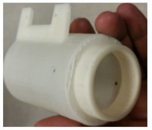
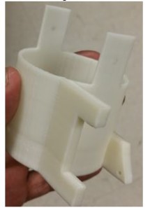
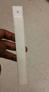
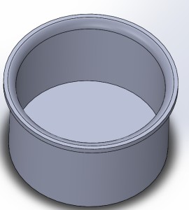
Before making our design, there were several parameters that we had to take into account such as ensuring that the attachments fit the ducted fans. For one we needed to keep the attachments as light as possible to not add on too much weight on to the vehicle however we could not for too light for several reasons. The parts that were 3D printed needed to be no less than 2 mm thick. The reason for this is because the 3D printer that we were using could not print any less than that. We first had a prototype printed to see if we could use a 3D printed part that was the thin. Once we had printed it, we saw that the part was way too thin to use and was easily broken. In order to make sure that the attachments weren’t too thin to break, we increased the thickness to 2.54mm which is roughly .1 inches thick. Once we printed a small prototype, we saw that it was much more durable than the 2mm one and we were able to easily drill through it without breaking as seen in Figure 1. 

Figure 1  3D printed duct attachment 

duct ring

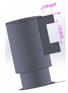
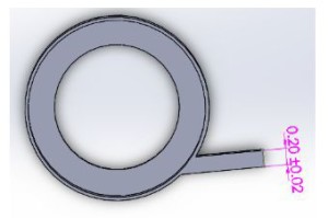
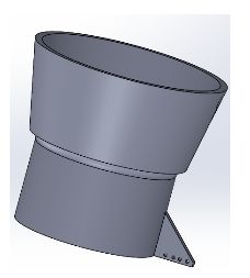
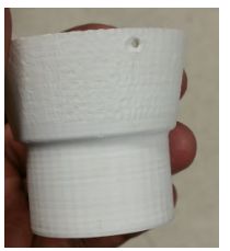
The next minor challenge that I had to consider was being able to mount on servos to the attachments. The servos were measured to have a height of 1.18 inches and needed to be mounted on to the cylindrical shape. We were initially going to make brackets and screw them in to lock the servos in place however it would be a challenge since we did not have a flat surface and we did not know if adding on screws into the attachment would affect the air flow. After consulting with my project manager, he suggested extruding a thin block out of the attachments and then mounting them onto their. I went with this suggestion and properly dimensioned the extrusion to fit the servo. Initially I designed the extrusion block to be roughly 1x .2x 2.25 inches in size. From there I made an inner cut that was .53x 1.19 inches so the servo can easily fit in (Figure 2). I had these printed and checked to see if both servo EDF could fit on to the attachment. Sure enough both did. In order to secure the servo, I had to drill into the extruded block. For this reason I made the block .2 inches thick, so it would not break off when drilling (Figure 3). Once making the holes, the servo was easily mounted on to the attachments.

Figure 2 CAD of thrust vector chamber with servo flaps (side view)

side view of chamber

Figure 3 CAD of thrust vector chamber with servo flaps (top view)

top view of chamber

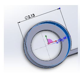
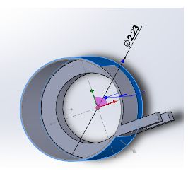
        Next we had to make sure that these attachments fit into our Electric Ducted fans. The ducted fans that we were using have an outer diameter of 53mm. I dimensioned the attachments to be slightly bigger than this in order for it to be able to slip on to the EDF. In order to not waste material and time, I had only one attachment be printed. Sure enough it did not fit and was way too tight to even slip on without damaging the attachment. I made designed the attachments to have roughly an inner diameter of 54.1mm which was approximately 2.13 inches (Figure 4) with an outer diameter of 2.23mm (Figure 5). Once making the adjustments, we were able to slip on the prototype into the EDF.

Figure 4  CAD of thrust vector chamber demonstrating inner diameter

idkwhatthisis      

Figure 5  CAD of thrust vector chamber demonstrating outer diameter

idkwhatthisis2

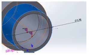
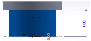
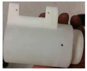
        Since we were going into thrust vectoring, I needed to make sure that the servos could move the attachments without causing any problems. One of the issues I noticed when designing the attachments was that after it rotating roughly 45 degrees, there was going to be a gap that would make air leak out, which could cause an addition issue when trying to stabilize the vehicle. To fix this problem, I made an inner cylinder to close off the gap and made it to have an outer diameter of 1.75 inches (Figure 6) and a length of 1 inch (Figure 7). Because of this, when the middle attachment rotated, there was no gap to leak air. The fabricated part can be shown in Figure 8A & B.

Figure 6 CAD of thrust vector chamber demonstrating inner diameter (second level)

idkwhatthisis3

Figure 7 CAD of thrust vector chamber demonstrating outer diameter (second level)

idkwhatthisis4

Figure 8A 3D Printed thrust vector chamber (side view)

idkwhatthisis5

Figure 8B 3D Printed thrust vector chamber (alternate view)

idkwhatthisis6

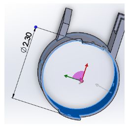
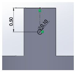
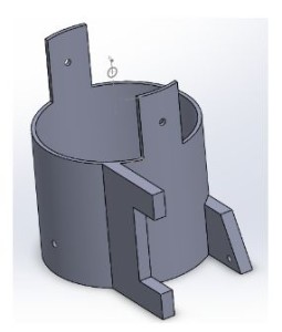
        Next was to design the middle attachment. The middle attachment was a much simpler design since much was learned from making the top one. This one just needed to have an inner diameter that was slightly bigger than the top one so it can fit and move. In order to give it a bit more space to move, this attachment had in inner diameter of 2.3 inches (Figure 9). In order to mount on this attachment to the top one, I made the mounts to be roughly 1 inch tall to compensate for the inch clearance that was given from the top attachment. I made a pilot hole on this that is in the center of the mount which was roughly .5 inches from the top of the attachment (Figure 10). An extrude block was added on to this attachment as the previous one, however an additional extrude block was added on in the back in order to have the servo joint attached on to it (Figure 11). There, the top servo was going to push and pull on to this attachment. Ideally this part was not meant to be this long, however we needed to give enough space for the servo. To control the bottom attachment. The fabricated part can be shown in Figure 12.

Figure 9 CAD of thrust vector chamber demonstrating inner diameter

idkwhatthisis7

Figure 10 CAD of thrust vector chamber attachments

idkwhatthisis8

Figure 11 CAD of thrust vector chamber (second level)

idkwhatthisis9

Figure 12 3D Printed thrust vector chamber

idkwhatthisis10

        Lastly we needed to make the bottom attachment. This was the simplest design since it was a funnel shape. In height, the funnel ended up being roughly two inches. As before, an extruded block was added on to this but just to connect to the servo, not to mount on (Figure 13). The fabricated part can be shown in Figure 14.

Figure 13 CAD of thrust vector chamber (lowest level)

idkwhatthisis11

Figure 14 3D printed thrust vector chamber (lowest level)

idkwhatthisis12

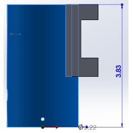
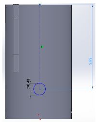
                Our second design was to control the yaw by adding flaps to counter the direction of the thrust. For this design, the top part was relatively similar to the previous one except it this not have an additional cylinder to close off any air gap. Also the height was made slightly smaller for the same reason of not having to worry about the air gap. The height of this attachment was roughly 3.83 inches with the same thickness and diameters of the previous design (Figure 15). The reason for this height again was because the EDF height including the coils was roughly 2.82 inches so I needed to make sure that there was a hole big enough to fit in the wires to power it on (Figure 16). In order to make this hole big enough, I needed to make sure there was enough space to make it. Also I needed to make sure that the flaps had enough space to mount on to the attachment.


Figure 15 CAD of thrust vector chamber demonstrating dimensions

idkwhatthisis13

Figure 16 CAD of thrust vector chamber with inner diameter

idkwhatthisis14

        There was much thought put into making the flaps to control the direction of the thrust. Initially the idea was to have the flaps go inside and the servo would rotate it however the problem with this was that it could not go in the middle of the attachment. The reason for this is because as the flap turned, there would be a big gap which would leak air out in a direction which would not be in our control. To attempt to solve this, we thought of making the top part of the flap bigger to block off the air gap. The problem with is now was that the top part was going to easily hit the attachment and would not let the flap rotate the way it should. The third idea was had was to remove the flap from being in the middle and putting it in the inner corner of the attachment. This did not work simply because the flap would not be able to rotate without hitting the attachment. After thinking it over with the project manager, we decided to mount on the flap outside of the attachment. I designed the flap to be able to mount on to the cylindrical attachment by making it the same shape. Some parts were trimmed off in order for it to not scrape when moving. The flap itself was designed as a prototype. It was made wide enough to cover the thrust of the EDF and long enough to redirect the thrust. The flap was made .2 inches thick in order to make it durable and hard to break as the EDF was going to be pushing against it. Similarly to the previous designs, and extruded part was added on simply to be able to attach the servo joint to push and pull the flap. The model and fabricated part can be seen in Figure 17A & B.

Figure 17A CAD of thrust vector flap

idkwhatthisis15

Figure 17B 3D printed thrust vector flap

idkwhatthisis16


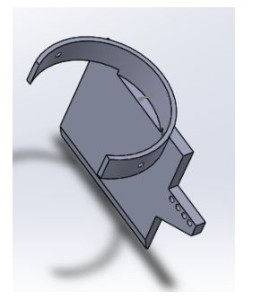
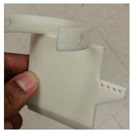
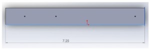
Lastly we noticed that if we were going to use all these attachments then we were going to have a problem with the legs since the attachments were long and were going to hit the floor. I modeled out new legs which were long enough so the attachments wouldn’t hit the ground when standing. These legs were approximately 7.25 inches long total but was given one inch clearance to mount them on to the vehicle (Figure 18). They were designed to be .2 inches thick so they would not break easily since it was supporting the weight of the vehicle. The fabricated part can be seen in Figure 19.

Figure 19 CAD of replacement legs                                  

idkwhatthisis17

Figure 19 3D printed replacement leg

leg

Though these attachments have been modeled and fabricated, we were not able to use any of them nor the servos simply because the added too much weight to the vehicle and made it too heavy to fly. Even adding on the servos alone made the vehicle too have so we could not use those however these concepts can be used for future semesters if they choose to go with a similar approach and taking account the weight ahead of time.

UFO Spring 2016 – EDF Area Coverage With Flap Length Calculations

Written and posted by: Luis Valdivia (Project Manager)

Table of contents:
Introduction
Approach
Formulas
Conclusion
Possible Solution


Introduction:
When attempting to angle the thrust coming from the Electric Ducted Fan (EDF), there is a risk of covering the ducted fan area to prevent vertical flight. This post will explain our research done to determine the maximum area allowed to control the aircraft without losing vertical thrust.


Approach:
Using middle school math, we can figure out the area of the flap size and the area of the duct.

Figure 1.1 demonstrates the area of the duct being covered by the flap, along with formulas for area. 

areamiddleschoolmath123

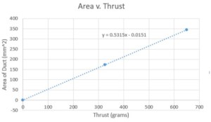
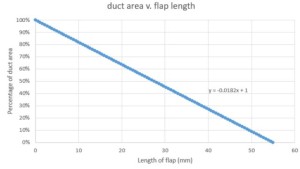
Because of the size of the EDFs, we will assume the length of the flap is fixed at 55mm. The Width of the flap will depend on the area of the opened duct, aka the area of the circle. For a fully opened duct (meaning no coverage of the circle) we can produce a maximum thrust of 650g with a flap of length 0mm. With a partially opened duct (meaning half of the circle is covered) we can produce half the thrust of 324.99g with a flap length of 27.5mm. Finally, for a fully closed fan duct we will produce 0g of thrust with a flap of length 55mm.
Inputting our 3 sets of values into excel, we can fit a linear line into our data plot to obtain the equation of our line. This equation will help us calculate more values to get a better understanding of the range between flap length and available output thrust.

Figure 1.2 Linear fit plot of Duct Area vs. Thrust (with equation of line)

AreavThrust123

Figure 1.3 Linear fit plot of Duct Area vs. Flap Length (with equation of line)

ductvflaplength123


Formulas

Area of duct = 2*π*(radius*percentage of opened duct)

Length of flap = 55mm(100 – percentage of opened duct)

Area of flap = length of flap * 55mm

Thrust (g) Area of duct Length (mm) area of flap (mm^2) % of open fan
650 345.4 0 0 100.00%
643.48137 341.946 0.55 30.25 99.00%
636.9815581 338.492 1.1 60.5 98.00%
630.4817463 335.038 1.65 90.75 97.00%
623.9819345 331.584 2.2 121 96.00%
617.4821227 328.13 2.75 151.25 95.00%
610.9823109 324.676 3.3 181.5 94.00%
604.4824991 321.222 3.85 211.75 93.00%
597.9826872 317.768 4.4 242 92.00%
591.4828754 314.314 4.95 272.25 91.00%
584.9830636 310.86 5.5 302.5 90.00%


Conclusion:

As you can see, the thrust output from the EDFs will beginning to decrease if we cover the duct. Although, from a previous blog post we mentioned the necessary thrust to lift the weight of the aircraft. The necessary thrust to lift a quadcopter weighing in at 1291g is 645.5g thrust for each EDF. From our table above, it seems like covering the duct at anything greater than 0.55mm will prevent our UFO from lifting off the ground.


Possible solution:

In order to continue the project with thrust vectoring, the EDFs will have to be swapped with fans of thrust greater than 650g. Another solution is to reduce as much weight as possible to lift the UFO and vector the thrust we a reasonably sized flap.  

Bluetooth Module Update Spring 2016

Written by: Anthony Becerril (Mission, Systems, and Test Engineer)

Posted by: Luis Valdivia (Project Manager)

Table of contents:

  • Introduction
  • Previous work
  • Current Progress
  • Additional Resources


Introduction:

The current UFO Quadcopter is being modified to communicate via bluetooth in addition to the already existing RC communication. The following will discuss previous work and current progress on bluetooth communication implemented with the quadcopter.


Previous Work:

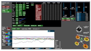
Previously the bluetooth module HC-06 was used in combination with the HK MultiWiii flight controller to monitor and control the quadcopter. A GUI is also provided alongside with the MultiWii controller and can be used to display information from the MultiWii from the following: triple axis gyro, accelerometer, barometer, magnetometer. Show below is the GUI’s display.

Figure 1.1 Multiwii Flight Telemetry GUI:

coolgui

The software can be found via the internet or the latest version found at this time can be downloaded here. Beyond that, in the past the Arxterra application has been used to sync up the phone to the desktop version of Arxterra and demonstrating the camera function. Further details on how bluetooth works can be found in the previous post on bluetooth from Fall 2015.


Current Progress:

Rather than pick up where previous work left off, discussion on whether a new approach was needed had happened. The results were using a new bluetooth module and researching for a phone application to help monitor and control the quadcopter.


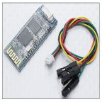
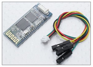
The bluetooth module we decided to use what the HC-02 android compatible module. Buying it from Hobby King also provided easier to use wires to connect it with the MultiWii board. When attaching to the quadcopter this module is easier to attach due to not having to deal with pins on a breadboard like you would with other modules.

Figure 1.2 Bluetooth Module and Connector:

bluetooth

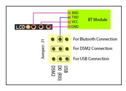
For setup, we followed the quick overview video as reference and first wire the module to the MultiWii controller. The wire connect as follows:

Figure 1.3 Wiring Diagram for Multiwii 328p:

bluetoothpinout

After setting it up, we power the MultiWii board to turn on the bluetooth module. When syncing up the module, it initially blinks due to not being paired to any device yet. When seeking to pair it is highly recommended to use an android device. When pairing look for the device, “HC-02” of the devices available. Then there is a prompt to input the pairing code which by default is 1234. This code can be changed with some research online. If pairing was successful then the bluetooth module should now be a solid light rather than be blinking. Now the module is paired and ready to be used with android applications.


This is a big step in communications due to the final goal of being able to control the quadcopter via phone application. Further research is going to be done to implement a third party application. This will then lead to being able to do the same with the Arxterra android application.


Additional Resources:

Previous Blog Post: Learning To Use a Bluetooth Module (Fall 2015)

Previous Blog Post: Bluetooth Interface to Arxterra Application (Spring 2015)

Multiwii MWC FC Bluetooth Module (HC-02)

Multiwii Software

MultiWii 328P + Bluetooth Module Quick Overview

PCB Design: Schematic – Spring 2016

Posted by: Luis Valdivia(Project Manager)

Written by: Kevin Nguyen(Electronics and Controls)


Table of Contents:

  • Introduction
  • Full EagleCAD Schematic
  • Step-Down(Buck) Switching Regulator
  • Servo Status Indicator
  • PCA9685 Connections
  • 3-Pin Headers for Servos and Lightshow
  • Pin Headers for Low Voltage Alarm and Bluetooth


Introduction:

One of the main tasks of the Electronics and Controls Engineer is to design the circuit for the PCB. This post will explain the reasonings behind the chosen components on our PCB.

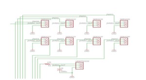
pcbschematic1.1

Fig 1.1 Full EagleCAD Schematic

This is the full schematic for UFO Quadcopter’s PCB. Further detail will be shown in the following figures.

pcbschematic1.2

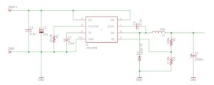
Fig 1.2 Step-Down(Buck) Switching Regulator

Tasked with redesigning the PCB from last semester, I chose to replace their adjustable LDO voltage regulator with an LMR14050 buck converter. The reason for this is because LDO regulators lower voltage by burning excess power while buck converters lower voltage by storing the excess power. For the quadcopter’s circuit, a 5V output is required from a 14.8V supply. Dropping that much voltage using an LDO will waste a lot of power. Using the buck converter, the supply voltage will be able to drop down to 5V while maintaining enough current to power the PCA9685, servos, and light show. Capacitors are placed in parallel with the input and output to smooth the ripples since switching circuits may cause some fluctuation. The inductor is a storage device used for storing energy. The size of the inductor will determine the current output of the buck. The LMR14050 can output a maximum of 2A, which will be enough to power the servos and light show. The resistor network on the right side of the buck is used to adjust the voltage. The values I used will result in a regulated 5V output.

pcbschematic1.3

Fig 1.3 Servo Status Indicator

This is a simple LED status indicator. It is connected to the same node that powers the servos. If the LED is lit, the servos should be powered on. The resistor is used to lower the current to protect the LED. With a constant voltage of 5V, the higher the resistance the lower the current.

pcbschematic1.4

Fig 1.4 PCA9685 Connections

The PCA9685 is the same chip used within the Adafruit Servo Driver. Since weight is a major issue for our project, I chose to implement the servo driver in our PCB so that we won’t have to add a third board to our setup. The left side of the PCA shows the connections for power and input. The right side is the PWM outputs for controlling the servos and light show. The PCA is connected to the MultiWii through I2C. The MultiWii is the master device and the PCA is the slave device. The Serial Data and Serial Clock signals from the MultiWii will be able to control all 8 servos and light show. The A0-A5 pins are used to set the address of the PCA. Since we are only using 1 slave device, I grounded all addressing pins which would set the PCA address to 0.

pcbschematic1.5

Fig 1.5 3-Pin Headers for Servos and Lightshow

8 3-Pin Headers are included for the servos. 4 for the servos rotating in the X direction and 4 for the servos rotating in the Y direction. A 3-Pin Header is also used for the light show. Each header includes a pin for data, power, and ground. The control signal will be coming from the PCA9685. These components will be powered by the regulated 5V from the buck.

pcbschematic1.6

Fig 1.6 Pin Headers for Low Voltage Alarm and Bluetooth

To keep things nice and tidy, I made pin headers on the PCB for the voltage alarm and the bluetooth module. This will hold all the components on the board and keep things from swinging around during flight.

UFO Light show setup

Posted by: Luis Valdivia (Project manager)

By: Anthony Becerril (Mission, Systems, and Test Engineer)

Table of contents:
    Intro
    Step 1: Hardware via Circuit
    Step 2: Software via Arduino integration
    Additional Resources


Intro:

This UFO Quadcopter post is in regards to the custom light show that is created through use of a 24 LED Adafruit NeoPixel Ring and follows along previous light show posts. The following will break down the proper setup for hardware and software and additional resources available.


Step 1: Hardware via Circuit

The first step consists of setting up the appropriate circuit to properly power the ring. The following setup is emulated via breadboard although it is to be implemented onto the Printed Circuit Board (PCB) for efficiency and optimal space on the quadcopter. Protection of the ring is important for the lifetime of the LEDs. As stated by the Adafruit NeoPixel Best Practices, The following should be followed:


  • 1000 microfarads capacitor should be added in parallels to power and ground terminals
  • 300-500 ohm resistor between arduino data output to neopixel data input
  • Minimize distance between arduino and ring
  • Avoid connect ring to a live circuit. If necessary, connect ground first, then power, then data. Disconnect in reverse order.


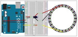
Other practices are listed along with more details on powering, library installation, and more. The link should be thoroughly explored before moving forward. The ones listed are important for this specific setup mainly due to the high voltage battery and making sure the appropriate precautions are taken. Figure 1-1 (below) gives an overview of our circuit used.

Figure 1-1 (Fritzing diagram)

lightshow

We only used 3 terminals of the ring: one power, one ground, and one data. The power supply for the emulation is a 5 volts power supply whereas when using the PCB we will be implementing such components to step down the LiPo battery used to power the quadcopter.


Step 2: Software via Arduino Integration

After completing the hardware, software comes next through use of the Arduino IDE. Following the Arduino Library installation, the Arduino software is now able to test the ring with the “strandtest” example code to result as follows:


https://youtu.be/qTRpvA696YY


From all this, the possibilities of different lights show are many when considering the many different patterns available. Next steps are creating a code to be operational via bluetooth then having successful Arxterra application control for a custom light show settings.


Additional Resources:

Previous Blog Post: How to Light Show (Spring 2015)

Previous Blog Post: Creating Neopixel Ring Light Show (Fall 2015)

Adafruit NeoPixel Ring – 24 x 5050 RGB LED with Integrated Drivers

Adafruit NeoPixel UberGuide

UFO Torque Test Spring 2016

Posted by: Luis Valdivia (Project Manager

By: Anthony Becerril (Systems Engineer)

Table of contents:

  • Test objective
  • Test Procedure and Criteria
    • Preliminary work
    • Procedure
  • Results
  • Conclusion
    • Video
  • Appendix


Test Objective:

To create stable flight, the current quadcopter must not have yaw rotation being created by the Electric Ducted Fans (EDFs). This torque test will measure the necessary torque to counter the yaw rotation that exists. Theoretically, this torque will eliminate the yaw rotation and the counter torque will be produced via an additional fan to be implemented.


Test Procedure and Criteria:

Preliminary Work:

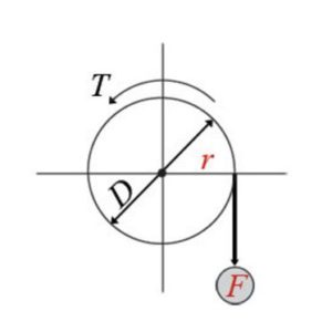
The torque seeked in this experiment will be calculated as follows:

Torque = F*r=F*(D/2)


r: radius; distance between center of rotation
D: diameter

F: force; force point

Figure 1.1 Representation of Torque setup:

Torque

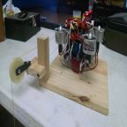
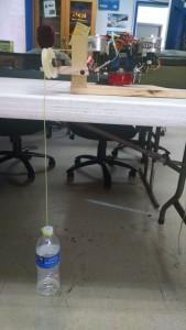
Figure 1.2 Set up used on UFO quadcopter:

IMG_20160403_161323392

The setup built for this testing required the following:

  • A pulley system to support weight like that of a full water bottle
  • A lazy-susan-like platform for quadcopter to spin on
  • An adjustable weight to vary on pulley during testing (i.e. water bottle)
  • A latching system to prevent the quadcopter from flying


Procedure:

The procedure to execute this test is as follows:

  1. Have fully charged battery ready [Appendix A]
  2. Upload corresponding Arduino IDE code to Arduino Uno
  3. Properly connect all necessary wires on quadcopter except for the battery [Appendix B]
  4. Place the quadcopter onto the set up turntable. Make sure the hooks are properly attached
  5. Have pulley weight properly attached to one of the EDFs
  6. Have potentiometer set to max before plugging in battery
  7. Plug in battery
  8. Tune potentiometer to turn on angle. Wait for calibration as indicated by the beeping code [Appendix C]
  9. Continue tuning potentiometer to higher thrust. Observe yaw rotation.
  10. If rotation exists, add more water to bottle. Continue this step until no rotation
  11. Take final weight and calculate final torque using the formula:

Torque=9.8ms2*radius *weight

Radius = 4.5” → 0.1143m

Weight= weight of object in Kg


Results:

Torques that were listed must have demonstrated rotation on the setup to be considered valid for our data collection.


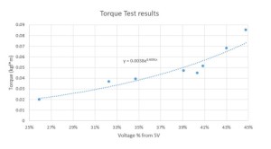
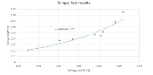
Table 1.1 Data collected from eight tests:

Test # mass(kg) of bottle after throttle % from pot Voltage (V) to the ESC Torque (kgf*m)
in class demo 0.0609 43.12% 2.16 0.068216526
1 0.018 25.90% 1.30 0.02016252
2 0.035 34.70% 1.74 0.0392049
3 0.04 40.33% 2.02 0.0448056
4 0.033 32.26% 1.61 0.03696462
5 0.042 39.10% 1.96 0.04704588
6 0.046 40.86% 2.04 0.05152644
7 0.076 44.77% 2.24 0.08513064

Figure 1.3 Plotted points torque v. voltage percentage from 5v to the ESC:

Percentage

Figure 1.4 Plotted points torque v. voltage provided to the Electronic Speed Controllers:

Voltage

Conclusion:

In conclusion we were able to gather multiple data points in our torque tests. Plotting our data points in excel, we can see the exponential trendline of the relation between torque of the quadcopter and voltage provided to the Electronic Speed Controller. These data points will help us understand how to maintain stability by producing our own counter torque. Using the 5th fan approach, we can determine what find to buy, based on necessary thrust to counter yaw torque. 

Click here for a video of the torque set up in action!

Appendix:

A. Battery Charging Manual

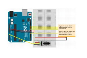
B. Wiring Diagram for Torque Test

Figure 1.5 fritzing diagram for torque test electronics:

FRITZING

Figure 1.6 cable tree of electronics:

WIRING DIAGRAM

C. Electric Speed Controller beep code

             Beep codes can be used for troubleshooting ESCs.

LiPo Battery safety Spring 2016

Posted By: Luis Valdivia (Project Manager)

Written by: Kevin Nguyen (Electronics and Control)


Table of contents:

  • Introduction
  • Using the IMax B6AC LiPro Balance charger
    • Charging
    • Discharging
  • Using the Voltage monitor system
  • Battery safety bag


Introduction:

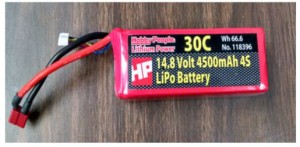
LiPo batteries are the most dangerous types of batteries in the world. They are very compact in size yet contain very high power. This high energy density allows them to power devices for longer periods of time compared to other types of batteries but also makes them very explosive. LiPo batteries may explode and catch fire if overcharged, undercharged, charged too fast, undercharged too fast, or punctured. Although this seems scary, if handled properly, LiPo batteries can be just as safe as any other battery and will outperform most other batteries. This blog post will help you minimize the risk and reap the rewards of LiPo batteries.LipoBattery safety

iMax B6AC LiPro Balance Charger:

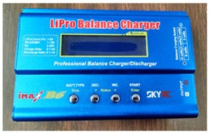
Most LiPo explosion incidents happen due to improper charging. This manual will help the user become familiar with the B6AC Lipo Charger to charge or discharge the lipo battery for the UFO quadcopter. Here are step-by-step guides on how to charge and discharge using the B6AC charger.

Lipo charger


  • Charging
      • Power charger from outlet with AC to DC adapter.
        • Once the charger is plugged into the wall, it should automatically turn on.  
      • Sift through the different modes using the DEC./◀ and INC./▶ buttons and through the options using the START/Enter button .
      • Select battery type using the BATT. TYPE/Stop button.
        • Be sure to select the correct battery type. There are different techniques for charging different batteries. Choosing the wrong battery type may burn down your house.
      • Select charging mode.
        • The preferable charging mode is Balanced Charging since it charges all cells evenly. To be able to use this mode you must have a balance connector on your battery. This is used to detect the voltage levels of each individual cell so that the charger can charge the appropriate cells depending on its level.
      • Select charging current.
        • More charging current will result in a faster charge. The general rule is to use the same value as the rated capacity(i.e. 4500mAH = use 4.5A charging current). It is acceptable to select a lower charging current, but do not choose a higher charging current unless specified in your batteries’ specs. Charging current may be limited by your AC to DC adapter. Since our wall adapter was only capable of producing 1A, we charged with a 1A charging current which might take some time.
      • Select battery cell count.
        • i..e. 4 cell battery = 4S
      • Plug the balance connector into the appropriate location on your charger depending on the amount of cells of your battery.
        • Pay attention to polarity.
      • Connect positive and negative ends of battery to charger.
        • An adapter is necessary to connect the two.
        • Connect the adapter to the charger before connecting the battery; this is to prevent shorting the battery. Shorting for long periods of time may cause fires.
        • When disconnecting, take the battery off first before the adapter; this is to prevent shorting the battery.
      • Once everything is plugged in and the correct options are selected, press and hold the START button for 3 seconds.
      • A screen should appear showing the amount of cells the battery is reading vs. the amount of cells the user set for charging.
        • If these two values match(R=S), press START/Enter to begin charging.
        • Once the battery is fully charged, the battery charger will beep to alert the user. Never charge past 4.2V per cell.
        • When storing the battery, it is best to charge no higher than 3.7V.   
      • While charging, the DEC./◀ and INC./▶ buttons can be used to view total voltage or individual cell voltages.
      • Press the BATT. TYPE/Stop button to stop charging.


  • Discharging
  • Select battery type.
    • Select discharge mode.
    • Select discharge current.
    • Press and hold Start for 3 seconds to begin discharging.

Note: Charging and Discharging too fast may damage the battery. Double check the charging/discharging rates to make sure it is compatible with your battery.                


Voltage Monitor Alarm System:

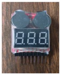
To prevent the battery from discharging to dangerous levels, a voltage monitor alarm system is used to alert the user of low voltage levels. Below is a quick setup guide for the low voltage alarm.

Lipo alarm

  • Connect the Balance Charging Connector to the Alarm.
    • The back of the alarm has labels showing the connections of each pin. Make sure the polarity is correct.
      • Once the Alarm has been successfully installed, an initial beep will sound to indicate that it is operating properly.
  • Press button at the top of the Alarm to select the lower limit of the voltage level.
    • This voltage level is used to compare against each cell of the battery. Once a cell goes below this value, the alarm will go off until removed.
    • LiPo battery cells should never go below 3V. It is recommended to set the lower limit to 3.2V to give some cushion time to remove the battery from the device.
  • After the device is connected to the battery, the 7-Segment display will display the value of the battery as well as the value of each individual cell.


Battery Safety Bag:

safety bag

When not in use, it is recommended to store the LiPo in a battery safety bag. In the case of an explosion, these bags are flame retardant and will prevent the fire from spreading. Only one battery should be stored in each bag. If more than one is stored in a bag, the effectiveness of the bag will be reduced and risk of burning down your house will increase. Stop using batteries that appear to be damaged. Overcharging or undercharging may cause gases to leak and make the battery appear puffy. The chemicals in the battery will ignite when exposed to air.
Works Cited:

  1. “The World’s Most Dangerous Battery.” The World’s Most Dangerous Battery. N.p., n.d. Web. 26 Mar. 2016. <http://www.atbatt.com/batterytimes/dangerous-battery>.
  2. “A Guide to Understanding LiPo Batteries – Roger’s Hobby Center – Radio Control (R/C or RC) Cars, Boats, Airplanes, Puzzles, Plastic Models, & Trains – Saginaw, MI.” A Guide to Understanding LiPo Batteries – Roger’s Hobby Center – Radio Control (R/C or RC) Cars, Boats, Airplanes, Puzzles, Plastic Models, & Trains – Saginaw, MI. N.p., n.d. Web. 26 Mar. 2016. <http://www.rogershobbycenter.com/lipoguide/>.
  3. N.p., n.d. Web. <https://www.pololu.com/file/download/iMAXB6ACmanual.pdf?file_id=0J525>.

Spring 2016 Millennium Falcon Preliminary Design Document

BY:

Luis Valdivia (Project Manger)

Anthony Becerril (Systems Engineer)

Juan Mendez (Manufacturing Engineer)

Kevin Nguyen (Electronics Engineer)

Table of contents: 

  • Program Objective 
  • Level 1 Requirements
  • Level 2 Requirements
  • Design Innovation
  • Subsystem Requirements
    • Product Breakdown Structure
    • Electronics System Design
      • System Block Design
      • Interface Definition
    • Manufacturing Design
  • Design and Unique Task Descriptions


Program Objective:

The Program Objective of the Millennium Falcon is to produce a safe, low cost, and durable quadcopter using ducted fans. The Millennium Falcon quadcopter will allow user friendly connectivity to an RC controller or any smartphone device using the Arxterra application. The project shall explore multiple innovative design solutions for yaw control leading to stable flight during operation of quadcopter. Stable horizontal flight control will also be addressed, as a design feature. The aircraft will resemble the famous spaceship from the Star Wars movie franchise with a newly designed shell and programmable lights.

Mission Profile:

The Mission Profile for the Millennium Falcon is to complete a flight course outside out CSULB property. The Millennium Falcon quadcopter must maintain stable flight as it circles around a tree in the field across the Whaley Park Community Center. Before attempting flight, the aircraft must be registered with the Federal Aviation Administration to ensure a safe environment for others.  
Level 1 Requirements:

  1. The Millennium Falcon quadcopter team, aims to maintain flight stability.
  2. An enclosure box will protect battery.
  3. A new Printed Circuit Board (PCB) must be re-designed.
  4. New shell for aircraft intends to resemble aesthetic requirements.
  5. Millennium Falcon quadcopter must have longer landing legs to support vehicle.
  6. Quadcopter is expected to implement user input from wireless communication.
  7. The Millennium Falcon quadcopter must display a programmable light show during flight.
  8. Quadcopter will perform designated flight path while meeting safety requirements
  9. Purchases and services for material items must not exceed budget.


Level 2 Requirements:

  1. The Millennium Falcon quadcopter team, aims to maintain stability by using a fifth Electric Ducted Fan (EDF) for yaw rotation control. If side fan solution is not implemented, EDF orientation, specifically bracket angle, will be optimized for Millennium Falcon quadcopter stability during flight.
  2. A battery enclosure box must structurally support the weight of the battery and protect it from impact.
  3. New PCB will be required to keep all wiring internal and not exposed. Crystal oscillator, resistors, capacitors will be internally designed contrary to previous semesters design.
  4. New shell casing will meet aesthetics by resembling the Millennium Falcon spaceship from the Star Wars movies. New shell casing also will feature a latching system to secure shell onto Millennium Falcon quadcopter frame.
  5. Removable landing legs must support the entire weight of the vehicle and lift it at least one inch off the ground.
  6. Wireless control of the Millennium Falcon quadcopter will be done by communicating via the Arxterra smartphone application supported on both android and apple as well as via bluetooth remote control.
  7. The Millennium Falcon quadcopter light show must be customizable via Arxterra smartphone application.
  8. The Millennium Falcon quadcopter will perform designated flight path at the CSULB traffic circle while meeting requirements set by the Federal Aviation Administration (FAA) , Unmanned Aircraft Systems (UAS) and College of Engineering (COE).
  9. All purchases and services cannot exceed $400.00 with the guidance of project manager and customer approval.

Design innovation:

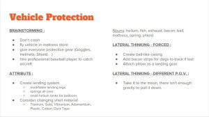
Below you can see the creative design process used in the creativity exercise.

Creative solution for vehicle protection: 

Creative Desing

Creative solution for controlling yaw rotation:

Creative Desing2

Subsystem Requirements:

Product Breakdown Structure (PBS):

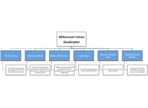
Below in the product breakdown structure, all components of focus are outlined with details explaining their purpose.

pbs

Electronics System Design:

Wireless Communication

  • An RC control will be created to control the Millennium Falcon quadcopter.
  • A smartphone application will be implemented to control the Millennium Falcon quadcopter. This application will be compatible with android and apple mobile devices.

Light Show

  • Light show must be controlled through Arxterra application.

5th Ducted Fan

  • 5th EDF must have enough thrust to counter the yaw rotation.

Battery

  • Since 5 EDFs are used this semester, battery must be able to supply power to 5 motors.  

New PCB

  • All components must lie within the PCB.

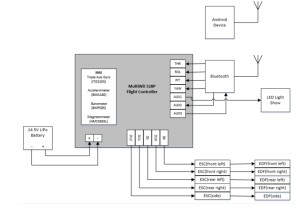
System Block Diagram:

sys block


This is the Signal Block Diagram for the Millennium Falcon Quadcopter. To maintain stability during flight, the microcontroller will constantly read data from the sensors and the data would then be analyzed using a PID algorithm. The PID controller would determine how much power to supply to the ESCs to keep the Quadcopter in a stable position. The ESCs are directly connected to the Electric Ducted Fans and will control the speed accordingly. The microcontroller will be setup with a bluetooth module for communication with any mobile device. As an alternative to bluetooth communication, an RF transceiver will be connected to an input pin of the GPIO. A Remote Controller will be designed to communicate with the RF transceiver to control the quadcopter. The advantages of using radio communication instead of bluetooth communication is that radio waves are capable of travelling much longer distances than bluetooth. A 14.5 V LiPo battery will be used to supply power to the device.

Interface Definition:

Resource Map

MultiWii 328p Bluetooth ESC LED
1 3.3V Vcc
2 A0
3 A1
4 A2
5 AX1 Vin
6 AX2(RX1) RXD
7 AX3(TX0) TXD
8 AX4/D3
9 BAT
10 D10 Front Right ESC
11 D11 Rear Right ESC
12 D12 Side ESC
13 D2
14 D3 Rear Left ESC
15 D9 Front Left ESC
16 D13
17 LCD
18 PIT
19 PSE
20 PWR
21 ROL
22 THR
23 YAW
24 GND GND GND


Based on last semester’s resource map, the pin connections for the components will be similarly placed with addition to the 5th ESC that will be used for yaw control. The LED is moved to Auxiliary Pin 1 to make room for the 5th ESC. Pin layout for the sensors are not needed since they are embedded within the microcontroller.


Manufacturing Design:

Lightshow

  • Mount neopixel light ring under the battery casing.

Electric Ducted Fan

  • A 5th fan will be purchased and mounted on to the side of the Millennium falcon quadcopter.
  • An additional bracket will be designed on Solidworks and 3D printed.

Picture of Electric Ducted Fan (EDF):

Fan1

Picture of prototype EDF bracket:

Fan2

Orientation (Alternate solution for yaw control)

  • A series of case studies will be performed in order to determine an accurate angle to tilt the ducted fans.
  • Additional brackets may be designed and 3D printed if necessary to replace the current ones.

Battery Protection


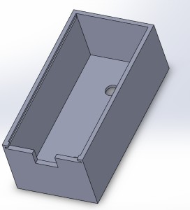
  • A protective case will be designed on Solidworks and 3D printed. The case will be dimensioned to fit the applicable battery which will be used.
  • The case will be tested in order to determine if it can withstand impact without damaging the battery.

Picture of battery enclosure prototype:

Battery case prototype


  • A lid to close off the battery will be designed using Solidworks and be 3D printed. The lid will be designed to have landing legs added or removed. The lid and legs will be tested if they can support the Millennium Falcon quadcopter.

Picture landing leg prototype:

Legs


Printed Circuit Board

  • PCB will be laid out and have components properly mounted on.
  • PCB shall be mounted on to the current Millennium falcon frame.

Shell Casing

  • Shell will be modeled to look the the Millennium Falcon. Techniques used in prior semesters will be used such as using foam to fabricate the mold and then vacuumed. Previous semester reference
    • Additional brackets will be designed and 3D printed in order to be added onto the current frame which will serve as mounting brackets for the shell.
    • Holes will dimensioned to be bigger in order to make more space for the ducted fans.
    • A 5th hole will be cut out in order to make space for the additional bracket and ducted fan.

Picture of Millennium Falcon prototype shell:

MF Shell


Design and Unique Task Descriptions:

Task: Landing Legs must be able to support more than the estimated mass of the quadcopter.

Solution: Manufacture legs of best material in mass and strength combination.


Task: Test wireless control capabilities.

Solution: For bluetooth and RC control, test signal strength for best control.


Task: Power complete quadcopter electronics system.

Solution: Upon quadcopter completion, choose a battery best fit for quadcopter.


Task: Create quadcopter stability during flight.
Solution: Test EDFs thrust capability and trial and error placement and direction of EDF .


Cite references:

  1. Huynh, Tien-Phuc. “UFO Shell’s Production.” Arxterra. N.p., 6 Dec. 2015. Web. 18 Feb. 2016. <https://www.arxterra.com/ufo-shells-production/>.
  2. Arechiga, Danny. “Level 1 Requirements.” Arxterra. N.p., 16 Sept. 2015. Web. 11 Feb. 2016. <https://www.arxterra.com/level-1-requirements-4/>.
  3. Hatori, Ayaka. “Arxterra | Mission Objective and Level 1 Requirements.” Arxterra. N.p., 18 Mar. 2015. Web. 11 Feb. 2016. <https://www.arxterra.com/mission-objective-and-level-1-requirements/>.
  4. Hatori, Ayaka. “Mission Objective and Level 1 Requirements.” Arxterra. N.p., 8 Mar. 2015. Web. 11 Feb. 2016. <https://www.arxterra.com/ufo-intro/>.
  5. Vo, Tuan, and Elaine Doan. “Level 1 Requirements.” Arxterra. N.p., 21 Apr. 2014. Web. 11 Feb. 2016. <https://www.arxterra.com/level-1-requirements/>.

Spring 2016 Millennium Falcon Research

By:

Luis Valdivia (Project Manager)

Anthony Becerril (Mission, systems and test)

Juan Mendez (Design and manufacturing)

Kevin Nguyen (Electronics and Controls)

Table of Contents:

  1. Project Manager Research
  2. Mission, Systems and Test
  3. Design and Manufacturing
  4. Electronics and Controls
  5. Creativity Assignment


1. Project Manager Research:

Project Level 1 requirements:

Overview/Purpose: Highlight baseline qualitative requirements for the overall mission.

Mission  Objective(s) from previous semesters: Produce aircraft that performs flight path set by the customer. The aircraft must also maintain stability as it travels its flight path. To meet aesthetic requirements set by the customer, the vehicle must resemble a UFO or the Millennium Falcon as well as producing a light show

Mission requirements from previous semesters:

  • Complete the project before end of semester
  • Follow regulations and policies for the Federal Aviation Administration (FAA), Unmanned  Aircraft Systems (UAS) and College of Engineering (COE) health and safety.
  • Not exceed the budget
  • Aircraft will maintain stable altitude
  • Remote control aircraft and display light show
  • Meet aesthetic requirement set by the customer (look like a UFO or the millennium falcon).

Mishaps:

  • Not able to maintain stability due to uncontrolled yaw rotation thus failing flight path requirement.

Proposed solution for Spring 2016:

  • Correct yaw stability issue by performing case studies (if allowed by customer) of fans mounted at certain angles.
    • Design adjustable angle brackets.
  • researching counter rotating fans to correct yaw issue (if allowed by customer)
  • Review policies and regulations set by the aforementioned organizations.
  • Establish safety landing feature that will slowly land view at low battery voltage.
  • Design and Manufacture interchangeable landing leg system.


Project Budget:

Overview/Purpose: Keep track of budget to avoid overspending.

Budget based on previous semesters:

  • Work with cost estimate as an outline to follow this semester.
  • Preliminary budget based on previous  projects around $400

Mishap: None. Requirements were met by remaining under set budget.

Proposed solution(s) for Spring 2016:

  • Create spreadsheet that keeps track of budget for all vendors and components of the vehicle.
  • Weekly update main spreadsheet with all procurement details.
  • Emphasize consistent documentation format to make information easy to access during the semester.


Project Schedule:

Overview/Purpose: Set a work schedule to follow on a weekly basis throughout the semester..

Project schedule based on previous semesters.

  • Use level 1/2 requirements to establish appropriate schedule .
  • Keep track of time invested each week for all members.
  • Include status and completion for each member.

Proposed solution(s) for Spring 2016:

  • Document progress every time an action item is closed.


EVALUATION RUBRIC

  1. Is the requirement, Quantitative, Verifiable, and Realizable?
  2. Is the requirement located at the correct level (1 – program / Project)
  3. Is the requirement response to a higher level requirement or customer’s objective (Requirement Flow Down)? Is the linkage clearly defined?
  4. Does requirement provide links to source material?
  5. Does the requirement move the design process forward?
  6. Are equations used to calculate a requirement provided and are answers correct?
  7. The requirements that are missing are the hardest to discover and will be factored into your evaluation.
  8. Is language in the form of a requirement?
  9. Avoid multiple requirements within a paragraph (i.e., breakup statements that contain multiple requirements.)

Y= Yes

N= No

X= No answer needed

Level 1 Requirements based from previous semesters 1 2 3 4 5 6 7 8 9
Must complete the project before end of semester. Y Y N Y N N X Y X
Will follow regulations and policies for the FAA, UAS, & COE. Y Y Y Y N N X Y X
Must not exceed budget. (estimated $400 from last semester) Y Y N N N Y X Y X
Aircraft will maintain stable altitude while completing course. Y Y Y Y Y N X Y X
Remote control aircraft and display light show. Y Y Y N N N X N X
Meet aesthetic requirement set by the customer. Y Y N N Y N X Y X

Works cited:


  1. Arechiga, Danny. “Level 1 Requirements.” Arxterra. N.p., 16 Sept. 2015. Web. 11 Feb. 2016. <https://www.arxterra.com/level-1-requirements-4/>.
  2. Hatori, Ayaka. “Arxterra | Mission Objective and Level 1 Requirements.” Arxterra. N.p., 18 Mar. 2015. Web. 11 Feb. 2016. <https://www.arxterra.com/mission-objective-and-level-1-requirements/>.
  3. Hatori, Ayaka. “Final Documentation.” Arxterra. N.p., 13 May 2015. Web. 11 Feb. 2016. <https://www.arxterra.com/final-documentation-3/>
  4. Hatori, Ayaka. “Arxterra | Final Documentation.” Arxterra. N.p., 13 May 2015. Web. 11 Feb. 2016. <https://www.arxterra.com/executive-summary-final-project-documentation/>
  5. Hatori, Ayaka. “Mission Objective and Level 1 Requirements.” Arxterra. N.p., 8 Mar. 2015. Web. 11 Feb. 2016. <https://www.arxterra.com/ufo-intro/>.
  6. Mohideen, Shamir. “UFO Final Documentation.” Arxterra. N.p., 14 Dec. 2014. Web. 11 Feb. 2016. <https://www.arxterra.com/ufo-final-documentation/>.
  7. Mohideen, Shamir. “UFO Preliminary Project Documentation.” Arxterra. N.p., 28 Oct. 2014. Web. 11 Feb. 2016. <https://www.arxterra.com/ufopreliminary-project-documentation/>.
  8. Vo, Tuan, and Elaine Doan. “Level 1 Requirements.” Arxterra. N.p., 21 Apr. 2014. Web. 11 Feb. 2016. <https://www.arxterra.com/level-1-requirements/>.
  9. Teng, James. “UFO Preliminary Project Plan.” Arxterra. N.p., 30 Sept. 2015. Web. 11 Feb. 2016. <https://www.arxterra.com/ufo-preliminary-project-plan/>.
  10. Hatori, Ayaka. “Arxterra | Final Documentation.” Arxterra. N.p., 13 May 2015. Web. 11 Feb. 2016. <https://www.arxterra.com/executive-summary-final-project-documentation/>.
  11. Stapleton, Anne. “Final Project Progress Report.” Arxterra. N.p., 19 Dec. 2013. Web. 11 Feb. 2016. <https://www.arxterra.com/project-progress-report/>.
  12. Mohideen, Shamir. “Schedule.” Arxterra. N.p., 14 Dec. 2014. Web. 11 Feb. 2016. <https://www.arxterra.com/schedule/>.
  13. Teng, James. “UFO Project Summary.” Arxterra. N.p., 17 Dec. 2015. Web. 11 Feb. 2016. <https://www.arxterra.com/ufo-project-summary/>.


2. Mission, Systems and Testing Research:

LEVEL 2 REQUIREMENTS:

Overview/Purpose: Detail level 2 requirements in alignments with level 1 requirements made to complete mission


Level 2 Requirements from previous semesters:

  • Quadcopter frame and electric ducted fans
  • specify UFO diameter and weight
  • Fire protection
  • LED ring for light show
  • Use of Electronic Speed Controllers (ESCs)
  • Control system consisting of microcontroller and flight controller
  • wireless communication via phone application and bluetooth module
  • Landing gear equipment
  • Shell mold for UFO appearance
  • Achieve flight and specify elevation and flight speed
  • Provide sufficient power for classroom flight


Mishaps: Stable flight has yet to be achieved with certain requirements never initiated (landing gear, flight, fire protection,…)
Proposed Spring 2016 Solution: revise level 2 requirements and consider new ones if new level 1 requirements are made

DIGITAL SIGNAL CANCELLATION:

Overview/Purpose: Implementation of signal cancellation from a digital approach, specifically by inverting the signal


Digital Signal Cancellation from previous semesters:

  • Via Simulink, simple cancellation made via inverting signal (sine wave used)
  • Via audio recording, cancellation attempted by simultaneously playing sounds of original signal and inverted signal (guidance with matlab code)


Mishaps: Cancellation failed via audio recordings
Proposed Spring 2016 Solution: Discuss with team if further work is necessary; If approved look into researching noise cancellation for aircrafts

NEOPIXEL LED LIGHT SHOW:

Overview/Purpose: A lightshow on the Adafruit NeoPixel Ring controlled with a microcontroller, bluetooth module, and app


NeoPixel LED Light Show from previous semesters:

  • LED control circuit w/o bluetooth to test custom light shows
  • LED control w/ bluetooth module via bluetooth terminal app
  • Light show integration with arxterra code
  • Created function/code from scratch for programming lightshow


Mishaps: None; successful creation of programmable LED light show; tape lights considered and never revisited
Proposed Spring 2016 Solution: Consider investigation light functions to display battery life

BLUETOOTH INTERFACE TO ARXTERRA APPLICATION:

Overview/Purpose: how to use bluetooth to control the UFO via phone


Bluetooth Interface from previous semesters:

  • step-by-step procedure on testing a bluetooth module with simple LED example
  • via phone application and Multiwii controller, the UFO can be controlled wirelessly


Mishaps: None; successful bluetooth integration
Proposed Spring 2016 Solution: Consider using, editing, or remaking method of controlling the UFO

ESC CURRENT DRAW TEST:

Overview/Purpose: Calculations of current draw from EDFs for overall power consideration


ESC Current Draw Test from previous semesters:

  • Completed testing and tabled results


Mishaps: Upon shorting, an upgrade was made to replace the ESC for short time to maximum throttle
Proposed Spring 2016 Solution: Consider retesting to check for functionality

EDFs (ELECTRIC DUCTED FANS):

Overview/Purpose: Overview on Electric Ducted Fans (EDFs) bought and installed on the UFO.


EDFs work from previous semesters:

  • Specifications provided: Dr. Mad 50mm 10 blade EDFs
  • Calculation of thrust outputs at various throttle levels for each EDF
    • Completed testing and tabled results
    • not perfectly linear
  • estimated weight: 1100g; 1100g thrust =  60%-70%; conclusion: stable flight = > 70% throttle
  • Cancelling horizontal torque of EDFs
    • New Fans: too costly and couldn’t find one to fit UFO model
    • Fan Tilt: tilt for counter clockwise thrust; concluded tilt will prevent spinning
    • Air Ducts: implement louvers to redirect airflow
  • Testing done on best number of blades
  • Solidworks simulation done to see if air ducts will minimize rotation in same direction


Mishaps:

  • Calculations of blade positioning seem incorrect
  • Cancelling of horizontal torque failed
  • Testing number of blades only considered three and ten blades
  • Air duct testing did not resolve unwanted rotation

Proposed Spring 2016 Solution: Retake tests and specifications

WIRELESS REMOTE COMMUNICATION USING XBEE RADIOS:

Overview/Purpose: wireless communication between the UFO and the user via an XBee Radio


Wireless Remote Communications from previous semesters:

  • controller: joysticks controlling vertical and horizontal via potentiometers
  • XBee: configuration, data, interpretation
  • vertical testing: joystick up increased fans accordingly


Proposed Spring 2016 Solution:

  • Consider getting new EDFs

UFO SYSTEM BLOCK DIAGRAM AND ELECTRICAL SCHEMATIC:

Overview/Purpose: Provided system block diagram and electrical interface diagram of UFO


System Block Diagram and Electrical Schematics from previous semesters:

  • outlines system block diagram
  • corresponding wiring diagram for system block diagram outlined


Mishaps: upon visual inspection, there is room for improvement
Proposed Spring 2016 Solution: Update with any changes made this semester

EVALUATION RUBRIC

  1. Is the requirement, Quantitative, Verifiable, and Realizable?
  2. Is the requirement located at the correct level (1 – program / Project)
  3. Is the requirement response to a higher level requirement or customer’s objective (Requirement Flow Down)? Is the linkage clearly defined?
  4. Does requirement provide links to source material?
  5. Does the requirement move the design process forward?
  6. Are equations used to calculate a requirement provided and are answers correct?
  7. The requirements that are missing are the hardest to discover and will be factored into your evaluation.
  8. Is language in the form of a requirement?
  9. Avoid multiple requirements within a paragraph (i.e., breakup statements that contain multiple requirements.)

Y= Yes

N= No

X= No answer needed

Level 2 Requirements based from previous semesters 1 2 3 4 5 6 7 8 9
UFO will be created with quadcopter frame and electric ducted fans Y Y Y N Y N X Y X
UFO will have specific diameter and weight Y Y N N N N X Y X
UFO will be protected against fires N Y Y Y Y N X Y X
UFO will utilize LED ring for light show Y Y Y N Y Y X Y X
UFO will use Electronic Speed Controllers (ESC) Y Y Y N Y N X Y X
UFO will use a microcontroller and flight controller as control system Y Y Y N Y N X Y X
UFO will be able to communicate wirelessly via Arxterra application and bluetooth module with specific range Y Y Y N Y N X Y X
UFO will be equipped with landing gear Y Y Y N Y N X Y X
UFO will have shell to give likeliness to UFO Y Y Y N Y N X Y X
UFO to achieve flight with specific elevation and speed Y Y Y Y Y N X N X
UFO to provide enough power for flight around classroom Y Y Y Y Y N X N X


Works cited:

  1. Hatori, Aya. “UFO Level 2 Requirements.” Arxterra. N.p., 4 Apr. 2015. Web. 11 Feb. 2016. <https://www.arxterra.com/ufo-level-2-requirements/>.
  2. Vo, Tuan, and Elaine Doan. “Level 2 Requirements.” Arxterra. N.p., 21 Apr. 2014. Web. 11 Feb. 2016. <https://www.arxterra.com/level-2-requirements-2/>.
  3. Nunez, Marco. “Digital Signal Cancellation.” Arxterra. N.p., 23 Nov. 2015. Web. 10 Feb. 2016. <https://www.arxterra.com/digital-signal-cancellation/>.
  4. Nunez, Marco. “Custom Programmable LED Light Shows.” Arxterra. N.p., 14 Nov. 2015. Web. 11 Feb. 2016. <https://www.arxterra.com/custom-programmable-led-light-shows/>.
  5. Nunez, Marco. “Creating NeoPixel Ring Lightshow.” Arxterra. N.p., 8 Nov. 2015. Web. 11 Feb. 2016. <https://www.arxterra.com/creating-neopixel-ring-lightshow/>.
  6. Webster, Logan. “How To: Light Show!” Arxterra. N.p., 20 Apr. 2015. Web. 11 Feb. 2016. <https://www.arxterra.com/how-to-light-show/>.
  7. Mohideen, Shamir. “LED Tape Lights for the UFO.” Arxterra. N.p., 13 Dec. 2014. Web. 11 Feb. 2016. <https://www.arxterra.com/led-tape-lights-for-the-ufo/>.
  8. Nunez, Marco. “Learning To Use a Bluetooth Module.” Arxterra. N.p., 20 Oct. 2015. Web. 11 Feb. 2016. <https://www.arxterra.com/learning-to-use-a-bluetooth-module/>.
  9. Alhammadi, Ahmed. “Bluetooth Interface to Arxterra Application.” Arxterra. N.p., 8 Apr. 2015. Web. 11 Feb. 2016. <https://www.arxterra.com/bluetooth-interface-to-arxterra-application-in-progress/>.
  10. Winter, Nathan. “ESC Current Draw Test.” Arxterra. N.p., 13 Dec. 2014. Web. 11 Feb. 2016. <https://www.arxterra.com/esc-current-draw-test/>.
  11. Winter, Nathan. “Electric Ducted Fans.” Arxterra. N.p., 13 Dec. 2014. Web. 11 Feb. 2016. <https://www.arxterra.com/electric-ducted-fans/>.
  12. Winter, Nathan. “Dr. Mad 50 Mm 10 Blade EDFs.” Arxterra. N.p., 13 Dec. 2014. Web. 11 Feb. 2016. <https://www.arxterra.com/dr-mad-50-mm-10-blade-edfs/>.
  13. Winter, Nathan. “EDF Thrust Test.” Arxterra. N.p., 13 Dec. 2014. Web. 11 Feb. 2016. <https://www.arxterra.com/edf-thrust-test/>.
  14. Winter, Nathan. “Cancelling the Horizontal Torque Produced by EDFs.” Arxterra. N.p., 25 Nov. 2014. Web. 11 Feb. 2016. <https://www.arxterra.com/cancelling-the-horizontal-torque-produced-by-edfs/>.
  15. Hatori, Ayaka. “Electric Ducted Fans – Number of Blades TOS.” Arxterra. N.p., 6 Mar. 2015. Web. 11 Feb. 2016. <https://www.arxterra.com/electric-ducted-fans-number-of-blades-tos/>.
  16. Montano, Juan. “Implementing the Air Ducts.” Arxterra. N.p., 20 May 2014. Web. 11 Feb. 2016. <https://www.arxterra.com/implementing-the-air-ducts/>.
  17. Rice, Jake. “Wireless Remote Communication Using XBee Radios.” Arxterra. N.p., 20 Mar. 2014. Web. 11 Feb. 2016. <https://www.arxterra.com/wireless-remote-communication-using-xbee-radios/>.
  18. Stapleton, Anne. “System Block Diagram & Electrical Schematic.” Arxterra. N.p., 2 Dec. 2013. Web. 11 Feb. 2016. <https://www.arxterra.com/system-block-diagram-electrical-schematic/>.
  19. Ceballos, Salvador. “UFO System Block Diagram and Interface.” Arxterra. N.p., 8 Apr. 2015. Web. 11 Feb. 2016. <https://www.arxterra.com/ufo-system-block-diagram-and-interface/>.


3. Design and Manufacturing Research:

YAW Problem:

Overview/Purpose: The reaction wheels were to be fabricated in order for fix the Yaw problem


Research on previous semester work:

  • Group decided to make reaction wheels to solve the yaw problem.
  • Group decided that a cylinder design would work and that they should spin opposite of fans.
  • Determined that heavier material would produce more torque.
  • Group agreed to to use ABS plastic since it was the easiest to fabricate using a 3D printer
  • Fritzing diagram was developed
  • After receiving recommendations from the class president, the reaction wheels idea was scrapped and the group agreed to tilt the angle of thrust of the fans in order to mimic a quadcopter and fix the yaw problem.
  • Group decided to test if more blades on fan gave more thrust. They tested  3 blade fans vs 10 blade fans. They came to the conclusion that the 10 blade fan produced more thrust but ended up using a 5 blade fan because they did not have enough of the 10 blade fan to use.
  • From the previous semester it seems that the motor mounts required taping of the motors and to avoid this they had planned to use an acrylic block.
  • Solidworks was used to determine the airflow of the fans
  • Based on these simulations, it was determined that the air flows like an upside down whirlwind which would turn into a problem if they have another fan spinning the same direction. The airflow of two fans made the airflow go upward instead of straight down.
  • To fix this, the group decided to use an air duct to stabilize it. It seems like they still had a problem with the yaw and to fix this, they repositioned the air duct.

Mishaps

Proposed Solution for Spring 2016:

  • In order to speed up the process, we will be looking into changing the fans and will be performing different tests to see which fans work better. We may possibly get more fans or change the rotation of the fans.

UFO’s shell production:

Overview/Purpose: The purpose of the shell was to give the UFO a look that resembled the craft from the movie “ The day the Earth stood still”

Research on previous semester work:

  • Manufacturing Engineer worked with a Design Engineer to make the UFO Shell molding
  • 14 24x4x1 pieces of foam were glued together to make a piece big enough to make the mold.
  • Holes were then cut, though the group did not state how they determined the size and position of the holes and then painted the shell glossy gray.   
  • Group talked about mounting on a frame or shell and they agreed that frame mounting was better since it was cleaner and lighter and easier to work with.
  • They then researched the materials to construct the shell ( styrene or carbon fiber shell). They agreed to use Styrene since it was lighter and cheaper
  • A negative of the shell was created to be used on the UFO
  • Next they decided to vacuum form mold a shell. They had a shell from the previous semester and they were able to use it for the vacuum form molding. It proved to be a much better but they still had some issues  such as having a hole in the shell.
  • Their manufacturing Engineer made urethane foam mold on the lathe machine in the design lab. She did this by one inch by 1.5 inch of layers together with spray adhesives and waiting for them to bond. Next the holes for each motor were determined and done by using a 55mm drill press.
  • Next they used the plastic molding machine. Eight forms were made with each attempt adjustments were made to the mold. The shell was then painted silver.

Mishaps

  • They soon discovered that the lathe machine used to make the dome shape was 6 inches and would only provide 12 inches diameter. The shell diameter needed to be 15 inches.  To fix this, they cut the foam in half in order to make them separately then glue them back together. Two shells were made, one that was ⅛ of an inch and the other 1/16 an inch. After vacuuming the shell, the ⅛ ended up being too thick for the UFO so the group decided to stick to the 1/16 shell. (Fall 2015)
  • At first attempts the mold was left in high temperatures and became disfigured.(Spring 2015)
  • Apparently they attempted to removed the material from the lathe but it failed since they removed too much material. They had to remake the mold. (Spring 2015)
  • The group attempted to print out the ufo and then piece it together. Due of time constraints they were not able to get the mold right. They only got the prototype one and was considered to be 20 percent done.

Proposed Solution for Spring 2016:

  • We will model out our mold to look like the millenium falcon. Using the same techniques that previous semesters did, we will be making a mold for it but instead of making separate pieces to make it look like the ufo from “ The day the earth stood still”, we will be making different pieces to make it look like the Millenium falcon. We may end up making the bigger round piece the same way last semester did it, with the adjustments of the fans then bond on the additional pieces to make it look like the Millennium falcon. We will take precautions in order to not make the same mistakes from last semester such as speeding up the process using the lathe machine by taking the right dimensions and also not burning out the mold.

UFO’s PCB:

Overview/Purpose: To create a PCB and a surface mount device used to control the UFO and LED light show.


Research on previous semester work:

  • Group got rid of bundle of wires used to distribute the power to the ECS and LED’s
  • Labeling was added to the EagleCAD schematic so that everyone knew which part was which.
  • Copper pad was added around the board
  • Group decided to build a separate custom PCB for the battery protection of the circuit since the lithium polymer did not include a built in protection circuit.
  • They followed a protection circuit that was created by DIY Perks. They incorporated what they learned to their PCB and they combined the components required to protect the light show as well to the PCB.
  • Once silicon was applied to the carbon fiber mold, it took about 18 hours for it to cure.

Mishaps

  • When assembling the PCB the potentiometer was connected incorrectly but was quickly fixed. (Spring 2015)
  • The group wanted to have the Multiwii on top of the PCB with space in between but they did not have enough clearance to connect the Bluetooth module on top of the PCB. To fix this they used 90 degree male headers and then connected to the bluetooth module from the outside. (Spring 2015)
  • The group was missing a crystal oscillator. To fix this, they took another one and soldered it to the PCB. Test code worked but the custom code did not work, perhaps because the bluetooth module was syncing to the board properly. (Spring 2015)
  • Lastly they did not give the PCB enough space to distribute all current required to power the UFO. Connectors also broke while assembling it but they used wires to fix it.(Spring 2015)

Proposed Solution for Spring 2016: This semester, we will be ensuring that the PCB has enough space to make sure that current flows through smoothly. We will also be working on Soldering on the components properly. One thing that was notices was that some wires were not soldered on properly, therefore breaking off and possibly not making a proper connection.  We will also be insulating out wire components in order to not have a bundle of wires nested around.


Carbon Fiber Body:

Overview/Purpose: To build a carbon fiber body for the UFO using the design from the previous semester.


Research on previous semester work:

  • A silicon mold was made from the original 3D printed body and then the carbon fiber pieces were made from the mold.
  • A quarter of a mold was made since it is very expensive to make. apparently it is 25$ for two bottles.
  • 3D printed parts needed to be sanded down since undesired grooves were made while being printed.

Mishaps

Proposed Solution for Spring 2016: Not much modifications will be done to the carbon fiber body. The only improvement we are proposing is to add on a case for the battery since it is unprotected at the moment and want to protect it from getting damaged. Along with making a case we want to add on landing legs to it so the UFO will land safely instead of landing on the battery itself.

  1. Teng, James. “UFO Project Summary.” Arxterra. N.p., n.d. Web. 11 Feb. 2016. <https://www.arxterra.com/ufo-project-summary/>.
  2. Teng, James. “Reaction Wheel Research.” Arxterra. N.p., 26 Oct. 2015. Web. 11 Feb. 2016. <https://www.arxterra.com/reaction-wheel-research/>.
  3. Teng, James. “Reaction Wheel Material Trade-off Studies.” Arxterra. N.p., 29 Oct. 2015. Web. 11 Feb. 2016. <https://www.arxterra.com/reaction-wheel-material-trade-off-studies/>.
  4. Hatori, Ayaka. “Final Documentation.” Arxterra. N.p., 13 May 2015. Web. 11 Feb. 2016. <https://www.arxterra.com/final-documentation-3/>.
  5. Hatori, Ayaka. “Electric Ducted Fans – Number of Blades TOS.” Arxterra. N.p., 6 May 2015. Web. 11 Feb. 2016. <https://www.arxterra.com/electric-ducted-fans-number-of-blades-tos/>.
  6. Montano, Juan. “Implementing the Air Ducts.” Arxterra. N.p., 20 May 2014. Web. 12 Feb. 2016. <https://www.arxterra.com/implementing-the-air-ducts/>.
  7. Montano, Juan. “Determining the Number of Fans.” Arxterra. N.p., 16 Mar. 2014. Web. 12 Feb. 2016. <https://www.arxterra.com/determining-the-number-of-fans/>.
  8. Huynh, Tien-Phuc. “UFO Shell’s Production.” Arxterra. N.p., 6 Dec. 2015. Web. 12 Feb. 2016. <https://www.arxterra.com/ufo-shells-production/>.
  9. Sakurai, Catherine. “UFO Shell Trade off Studies.” Arxterra. N.p., 15 Apr. 2015. Web. 12 Feb. 2016. <https://www.arxterra.com/ufo-shell-trade-off-studies/>.
  10. Hatori, Ayaka. “Shell Molding.” Arxterra. N.p., 6 May 2015. Web. 12 Feb. 2016. <https://www.arxterra.com/shell-molding/>.
  11. Hatori, Ayaka. “Completed Project with Progress Update.” Arxterra. N.p., 13 May 2015. Web. 12 Feb. 2016. <https://www.arxterra.com/completed-project-with-progress-update/>.
  12. Vo, Tuan. “Building the UFO 1.02 (Code Name: George Michael).” Arxterra. N.p., 20 May 2014. Web. 12 Feb. 2016. <https://www.arxterra.com/building-the-ufo-1-02-code-name-george-michael/>.
  13. Huynh, Tien-Phuc. N.p., 16 Dec. 2015. Web. 11 Feb. 2016. <https://www.arxterra.com/ufos-printed-circuit-board/>.
  14. Hatori, Ayaka. N.p., 13 May 2015. Web. 11 Feb. 2016. <https://www.arxterra.com/pcb-design-battery-protection-circuit/>.
  15. Winter, Nathan. “Manufacture the Carbon Fiber Body.” Arxterra. N.p., 25 Nov. 2014. Web. 12 Feb. 2016. <https://www.arxterra.com/manufacture-the-carbon-fiber-body/>.


4. Electronics and Controls Research:

YAW Control:

Overview/Purpose: Prevent UFO from spinning uncontrollably by stabilizing the yaw rotation.  


Yaw Control from previous semester:

  • 3 Possible Ideas:
    • Reaction Wheel spins in opposite direction to cancel out yaw rotation.
    • Attach a 5th fan on the side to counter the rotation caused by the other 4 fans
    • Tilt fans.


Mishaps:

  • Several experiments show that the reaction wheel would not work.
  • A 5th fan on the side would disturb the symmetry of the UFO and cause additional problems.

Proposed Solution for Spring 2016:

  • Tilting the EDFs is the easiest way to cancel out the yaw rotation. More experiments will be needed to determine the angles best suited for our UFO.

PID Tuning:

Overview/Purpose: Determine the best coefficient values for our PID controller so that we would achieve the most efficient stabilizing effect.


PID tuning from Previous Semester:

  • Used “EZ-GUI Ground Station” app to find P,I,D gains.
  • Strapped UFO to inverted chair for safety and easy tuning process.


Mishaps:

  • none


Proposed Solution for Spring 2016:

  • Discuss with team if further work is agreed upon.
  • Possibly incorporate other types of controller designs besides PID for more efficiency. ex.LQR

Analog Noise Cancellation:

Overview/Purpose: Use analog components to design a noise cancelling circuit to reduce the noise of the UFO.


Analog Noise Cancellation from Previous Semester:

  • Designed a noise cancelling circuit.
  • The circuit receives the input signal through a microphone.
  • Input signal is sent through a non-inverting amplifier to boost the voltage to workable levels.
  • The boosted signal is then sent through an inverting amplifier to shift it 180 degrees.
  • After amplifying and inverting the signal, it is sent to a speaker to produce noise.


Mishaps:

  • Theoretically, when this output noise is played alongside the input noise, the 2 should cancel each other out. It did not work as expected.
  • The input noise and the output noise must precisely synchronize in order to cancel out each other. This proved too difficult to achieve.


Proposed Solution for Spring 2016:

  • Discuss with team if further work is agreed upon.

Experiment: Battery Discharge Characteristics and Voltage Monitor:


Overview/Purpose:

  • Determine how long battery will last while UFO is running at 80% throttle.


Battery Discharge Characteristics and Voltage Monitor from previous Semester:

  • Test circuit was designed to read the voltage levels of each cell within the battery.
  • The UFO was then connected to the circuit and turned on at 80% throttle while the voltage levels were being monitored.
  • Data shows that the battery cells reached undesired levels at around 10 minutes.
  • Voltage reader was then constructed as a warning indicator of low battery levels.


Mishaps:

  • none.

Proposed Solution for Spring 2016:

  • Discuss with team if further work is agreed upon.
  • Possibly design a safety landing feature, where the UFO will shut off all wireless communication with the remote controller and automatically land when the battery levels are low.

Multiwii ESC and Receiver Connections:


Overview/Purpose:

  • Documentation on how to connect the ESC and receiver to the microcontroller.


Multiwii ESC and Receiver Connections from previous Semester:

  • Instructional post on which connectors go into which pins of the microcontroller.


Mishaps:

  • none.


Proposed Solution for Spring 2016:

  • This post will be used as a guideline when installing our ESC’s and receiver.

PCB Design – Battery Protection Circuit:


Overview/Purpose:

  • Instructional video on creating a Battery Protection Circuit to prevent over-discharging.


Battery Protection Circuit from previous Semester:

  • The LiPo battery in our possession does not have a Protection Circuit.
  • Design of a Battery Protection Circuit shall be included in the PCB.


Mishaps:

  • none


Proposed Solution for Spring 2016:

  • This post will be used as a guideline to include a Battery Protection Circuit in our own PCB.
  • Possibly add a feature to safely land at low battery levels to prevent UFO from crash landing when the battery shuts off.

PID Control and Tuning:


Overview/Purpose:

  • Informative Post on PID Control


PID Control and Tuning from previous Semester:

  • Detailed instructions on how to PID tune.
  • Links included for PID controller download for Arduino IDE.
  • Instructions on altering files to be compatible with UFO.

Mishaps:

  • none


Proposed Solution for Spring 2016:

  • similar set up will be used for PID tuning.

Trade-Off Study: Battery


Overview/Purpose:

  • Comparison of different types of batteries to determine best battery for UFO.


Battery Trade-Offs from previous Semester:

  • Used same trade-off study from Spring 2014
  • Turnigy nano-tech A-Spec G2 met all required specifications.

Mishaps:

  • none


Proposed Solution for Spring 2016:

  • Create updated chart with more options.

Quadcopter PID Control:


Overview/Purpose:

  • Informative post on PID control.

PID Control from previous Semester:

  • A PID controller measures the error between the actual and desired values.
  • It then makes corrections to the system to reduce the error and make the actual value as close to the desired value as possible.
  • The speed and efficiency of the correction is heavily dependant upon the P, I, and D coefficients of the controller.
  • Lists of pro and cons of each coefficient is shown in the post.


Mishaps:

  • none.


Proposed Solution for Spring 2016:

  • very informative post on PID control.
  • will use for future reference.

Trade-Off Study: Motor Battery Selection


Overview/Purpose:


  • Comparison of different types of batteries to determine best battery for UFO.


Battery Trade-Offs from previous Semester:


  • Study was done comparing cost, weight, capacity, max discharge rate, max current draw, max flight time, and capacity/weight ratio.


  • MaxAmps LiPo was chosen due to the high capacity and cost advantage, as well as the higher current draw than any other options.


Mishaps:

  • none


Proposed Solution for Spring 2016:


  • Create updated chart with more options.

Final Controls Update:


Overview/Purpose:

  • Detailed results of Fall 2013 quadcopter. Recommendations for future UFO project members.


Final Controls Update from previous Semester:

  • future recommendations:
    • tune PID more accurately
    • prevent yaw rotation
    • tinyduino is hard, use a different microcontroller if possible
      • EDFs provide more thrust than anticipated, so the UFO can support a heavier microcontroller if needed
      • breakout board on tinyduino is 1mm, extremely hard to work with.


Mishaps:

  • PID needs better tuning to improve stabilization during hover and turn operations.
  • yaw rotation out of control. design something to counter it.
  • tinyduino is not easy to work with.


Proposed Solution for Spring 2016:

  • research more on PID tuning.
  • research angle tilt of fans to counter yaw rotation.
  • new microcontroller if budget allows.

Experiment: Prototype Test


Overview/Purpose:

  • Conducted tests to determine whether quadcopter meets requirements and whether updates need to be made to the design.


Prototype Test from previous Semester:

  • 3 Tests: Rotation, Lift, Tilt
    • Test A(Rotation) results:  it is noted that the yaw rotation is caused by an increase in acceleration. if the velocity of the fans is slowly increased the rotation will be reduced.
    • Test B(Lift) results: around 36% applied thrust is required to lift the UFO and maintain hover.
    • Test C(Tilt) results: tilting the UFO succeeded but the tilt may not be enough for it to turn in the desired direction.


  1. Arechiga, Danny. “YAW Control.” Arxterra. N.p., 12 Dec. 2015. Web. 12 Feb. 2016. <https://www.arxterra.com/yaw-control/>.
  2. Arechiga, Danny. “PID Tuning.” Arxterra. N.p., 11 Dec. 2015. Web. 12 Feb. 2016. <https://www.arxterra.com/pid-tuning/>.
  3. Arechiga, Danny. “Analog Noise Cancellation.” Arxterra. N.p., 2 Dec. 2015. Web. 12 Feb. 2016. <https://www.arxterra.com/analog-noise-cancellation/>.
  4. Arechiga, Danny. “Battery Discharge Characteristics and Voltage Monitor.”Arxterra. N.p., 16 Dec. 2015. Web. 12 Feb. 2016. <https://www.arxterra.com/battery-discharge-characteristics-and-voltage-monitor/>.
  5. Arechiga, Danny. “Multiwii ESC and Receiver Connections.” Arxterra. N.p., 26 Oct. 2015. Web. 12 Feb. 2016. <https://www.arxterra.com/multiwii-esc-and-receiver-connections/>.
  6. Hatori, Ayaka. “PCB Design – Battery Protection Circuit.” Arxterra. N.p., 13 May 2015. Web. 12 Feb. 2016. <https://www.arxterra.com/pcb-design-battery-protection-circuit/>.
  7. Ceballos, Salvador. “PID Control and Tuning.” Arxterra. N.p., 22 Apr. 2015. Web. 12 Feb. 2016. <https://www.arxterra.com/pid-control-and-tuning/>.
  8. Jackson, Anthony. “Battery.” Arxterra. N.p., 14 Dec. 2014. Web. 12 Feb. 2016. <https://www.arxterra.com/battery/>.
  9. Mohideen, Shamir. “Quad-copter PID Control.” Arxterra. N.p., 13 Dec. 2014. Web. 12 Feb. 2016. <https://www.arxterra.com/quad-copter-pid-control/>.
  10. Rice, Jake. “Motor Battery Selection.” Arxterra. N.p., 16 Mar. 2014. Web. 12 Feb. 2016. <https://www.arxterra.com/motor-battery-selection/>.
  11. Walth, Carlen. “Final Controls Update.” Arxterra. N.p., 18 Dec. 2013. Web. 12 Feb. 2016. <https://www.arxterra.com/final-controls-update/>.
  12. Walth, Carlen. “Prototype Testing Results.” Arxterra. N.p., 21 Dec. 2013. Web. 12 Feb. 2016. <https://www.arxterra.com/prototype-testing-results/>.


5. Creativity Assignment:

Random Nouns Generated:

  • Mattress
  • Helium
  • Shell
  • Bacon
  • Spring
  • Ball
  • Fish
  • Vehicle
  • Moon
  • Wing
  • Device
  • Mint
  • Kite
  • Wheel

How do we protect vehicle from crash landing damage/ hurting people?

  • Brainstorm
    • don’t crash
    • fly vehicle in mattress store
    • Slow down vehicle as it reaches certain height or battery voltage lowers
    • Give everyone helmets, protective vests, bubble wrap, safety goggles…
    • Hire professional baseball player to catch aircraft
  • Attribute
    • Create landing system
      • Add springs all over (the simpsons maggie)
      • modifiable landing legs
      • Small helium tanks to inflate balloons
    • Shell Material:
      • Titanium
      • Gold
      • Vibranium (Captain America)
      • Adamantium (Wolverine)
      • Plastic
      • Cotton
      • Duct Tape
  • Lateral thinking
    • Forced
    • Random Noun Generator:
      • Helium, Fish, Exhaust, Bacon, Dodge ball, Mattress, Spring, Shield
    • Create new casing to resemble a beach ball/ Dodge ball
    • Fish tail to control the vehicle.
    • Add Bacon strips for dogs (and hungry bacon lovers )to find in case we lose the vehicle
    • Use turtle shell, for battery protection
    • Attach Pillow as a landing gear
  • Different Point of View:
    • Send it to the moon, there isn’t as much gravity like earth to pull it down.

What can we do to control the Yaw rotation?

  • Brainstorm
    • tilt fans
    • alternate clockwise and counterclockwise fans
    • use reaction wheels
    • add wings
    • Have a volunteer counter rotation by hand
  • Attribute
    • heavier shell might be less prone to rotation
      • might reduce yaw rotation
  • Lateral thinking
    • Forced
      • Use coke and mentos propulsion
  • Diff POV
    • Build it in the future, use anti gravity propulsion
    • Fly the device on it’s side; now the yaw problem is a pitch problem
    • Use AI to stabilize itself
    • Build it in the past with no electronics, attach frame to a kite