Posts
UFO Torque Test Spring 2016
/in UFO, UFO Generation #6, Uncategorized/by Millenium_Falcon_LuisPosted by: Luis Valdivia (Project Manager
By: Anthony Becerril (Systems Engineer)
Table of contents:
- Test objective
- Test Procedure and Criteria
- Preliminary work
- Procedure
- Results
- Conclusion
- Video
- Appendix
Test Objective:
To create stable flight, the current quadcopter must not have yaw rotation being created by the Electric Ducted Fans (EDFs). This torque test will measure the necessary torque to counter the yaw rotation that exists. Theoretically, this torque will eliminate the yaw rotation and the counter torque will be produced via an additional fan to be implemented.
Test Procedure and Criteria:
Preliminary Work:
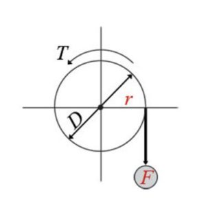
The torque seeked in this experiment will be calculated as follows:
Torque = F*r=F*(D/2)
r: radius; distance between center of rotation
D: diameter
F: force; force point
Figure 1.1 Representation of Torque setup:
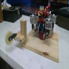
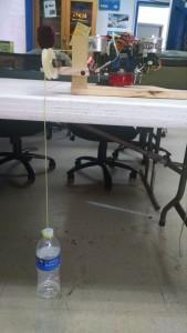
Figure 1.2 Set up used on UFO quadcopter:
The setup built for this testing required the following:
- A pulley system to support weight like that of a full water bottle
- A lazy-susan-like platform for quadcopter to spin on
- An adjustable weight to vary on pulley during testing (i.e. water bottle)
- A latching system to prevent the quadcopter from flying
Procedure:
The procedure to execute this test is as follows:
- Have fully charged battery ready [Appendix A]
- Upload corresponding Arduino IDE code to Arduino Uno
- Properly connect all necessary wires on quadcopter except for the battery [Appendix B]
- Place the quadcopter onto the set up turntable. Make sure the hooks are properly attached
- Have pulley weight properly attached to one of the EDFs
- Have potentiometer set to max before plugging in battery
- Plug in battery
- Tune potentiometer to turn on angle. Wait for calibration as indicated by the beeping code [Appendix C]
- Continue tuning potentiometer to higher thrust. Observe yaw rotation.
- If rotation exists, add more water to bottle. Continue this step until no rotation
- Take final weight and calculate final torque using the formula:
Torque=9.8ms2*radius *weight
Radius = 4.5” → 0.1143m
Weight= weight of object in Kg
Results:
Torques that were listed must have demonstrated rotation on the setup to be considered valid for our data collection.
Table 1.1 Data collected from eight tests:
| Test # | mass(kg) of bottle after | throttle % from pot | Voltage (V) to the ESC | Torque (kgf*m) |
| in class demo | 0.0609 | 43.12% | 2.16 | 0.068216526 |
| 1 | 0.018 | 25.90% | 1.30 | 0.02016252 |
| 2 | 0.035 | 34.70% | 1.74 | 0.0392049 |
| 3 | 0.04 | 40.33% | 2.02 | 0.0448056 |
| 4 | 0.033 | 32.26% | 1.61 | 0.03696462 |
| 5 | 0.042 | 39.10% | 1.96 | 0.04704588 |
| 6 | 0.046 | 40.86% | 2.04 | 0.05152644 |
| 7 | 0.076 | 44.77% | 2.24 | 0.08513064 |
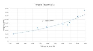
Figure 1.3 Plotted points torque v. voltage percentage from 5v to the ESC:
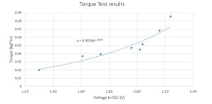
Figure 1.4 Plotted points torque v. voltage provided to the Electronic Speed Controllers:
Conclusion:
In conclusion we were able to gather multiple data points in our torque tests. Plotting our data points in excel, we can see the exponential trendline of the relation between torque of the quadcopter and voltage provided to the Electronic Speed Controller. These data points will help us understand how to maintain stability by producing our own counter torque. Using the 5th fan approach, we can determine what find to buy, based on necessary thrust to counter yaw torque.
Click here for a video of the torque set up in action!
Appendix:
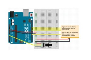
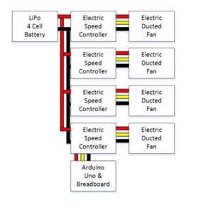
B. Wiring Diagram for Torque Test
Figure 1.5 fritzing diagram for torque test electronics:
Figure 1.6 cable tree of electronics:
C. Electric Speed Controller beep code
Beep codes can be used for troubleshooting ESCs.

