Spring 2016 3D SMD: Verification Test — Cable Fatigue
By: Christine Vu (Missions, Systems, and Test)
Table of Contents
Cable Test
A test will be conducted to determine that the bending radius will have a minimum bend radius of 10x its cable diameter.
Requirements
Section 1 EE400D Assembly
The SMD pick and place machine shall pick up and place down all SMT components provided by any EE400D PCB up until the end of Spring 2016.
Section 1.1.4
All moving cables using RJ25 connectors shall have a minimum bend radius of 10x its diameter (Telecommunications Industry Association, 2001).
Applicable Tools
| Equipment Type | Name (Brand) | Tolerance |
| Mitutoyo S/N 12519090 | Caliper | 0.001” |
| Measuring Tape | Stanley 33-425 Powerlock 25-Foot by 1-Inch Measuring Tape | +/- 3% |
Background
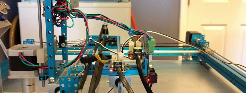
According to previous studies (Weaver & Gutierrez, 2015), wire fatigue may occur during repetitive movement. The Makeblock X-Y Plotter Robot Kit moves in a confined area with multiple repeated values of X-coordinates and Y-coordinates. Therefore, our project may be subject to repetitive movement that may cause damage to the cables.
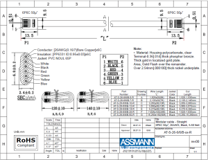
The Makeblock company overall lacks a large amount of datasheets for their parts, so it was difficult to determine the standards of their RJ25 cables and connectors. It was noted that it was a 6P6C connector, so we decided to reference Digi-Key’s supplier, Assman WSW Company, whose cable diameter size is 26 AWG. The datasheet is shown in Fig. 1.
Figure 1. Reference datasheet for AT-S-26-6/6/B-xx-R.
In addition, we referred to commercial telephone standards (Telecommunications Standard Association, 2001), which noted that wire bend radius should have a minimum of 10 times its cable diameter.
Due to the funding of this project, we will not imitate the rotary fatigue tests as done by Weaver & Gutierrez (2015). As a replacement of this test, we will measure the cable bend radii at each important area to assure compliance.
Diameter of entire cable = 6.8 ± 0.2 mm
Worst-case scenario = 6.6 mm
6.6 * 10 = 66 ± 0.2 mm = 2.59 ± 0.007 in.
Therefore, minimum bend radius shall be 2.59 ± 0.007 in.
Procedure
- Connect the wires attached to the X-Axis and Y-Axis.
- Control the Y-Axis and move to the farthest end of the plotter with respect to the PCB until the limiting switch is hit. Record the length of the cable.
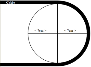
- Control the Y-Axis to the other side of the limiting switch. Record the bend radius as shown as the photo below.The bend radius will be measured at the curved cable touching the aluminum surface.
Figure 2. Obtained from: https://en.wikipedia.org/wiki/Bend_radius#/media/File:Bendradius.svg
Results
Locations
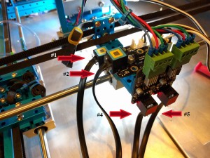
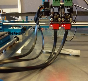
The locations of each measured area is shown below.
Figure 3. Cable #’s of the RJ25 cables.
| Cable # | Y-Limiting Switch (in.) | X-Limiting Switch (in.) | Requirement Met? (Y/N) |
| 1 | N/A | 3.843” | Y |
| 2 | N/A | 3.605” | Y |
| 4 | 4.587” | N/A | Y |
| 5 | 4.655” | N/A | Y |
Table 1. Cable Bend radii measurements.
Conclusion
Cables using RJ25 connectors can have a minimum bend radius of 2.59″ +/- 0.007″. The smallest bend radius was 3.605″, which is larger than the required amount. Therefore, this requirement is passed.
References
Assmann WSW Components. (2013). “Modular cable – Straight 6P6C 50u”, 26 AWG, Black, 5-50 feet”. Datasheet.
Telecommunications Industry Association. (2001). TIA/EIA-568-B.1: Commercial Building
Telecommunications Cabling Standard.
Weaver, J. , & Gutierrez, E. (2015). Comparing rotary bend wire fatigue test methods at different test speeds.Journal of Materials Engineering and Performance, 24(12), 4966-4974.

