FuzzyBear Spring 2020
Temperature Analysis And Cooling Of Fuzzy Bear Electrical Components
Author: Joshua Hurst
Table of Contents
Introduction
Due to the fuzzy bears enclosure, overheating could become a potential problem with varying magnitude. To tackle this issue, the primary source of heat radiating from the fuzzy bear must be identified. To identify this source of heat an infrared camera can be used to map out the hot spots of the robot while in motion, or after certain time intervals of being active. Then a cooling system and enclosure can be designed to dissipate or utilize the heat. Also, due to the fuzzy bears warming function heat can be diverted to the skin via liquid or air convection.
Thermal Study
Heat is transferred one of three ways by convection, conduction, and radiation. Convection is heat transfer through liquids or gases. Conduction is heat transfer by neighboring particles or particles in direct contact of each other. Radiation is unique in that it does require a medium to transfer its energy and can be done so through a vacuum via electromagnetic waves. The easiest analogy to describe each of the different types of heat transfer is to use a boiling pot of water as an example. The heat source of course is defined as the metal coils below the pot. Convection occurs when the water in the pot gains kinetic energy due to the water below it being heated by the pot. The water is not in physical contact with the heat source, but receives energy from neighboring water molecules. Conduction is the direct transfer of heat from the source itself. The pot directly touching the metal coils is an example of conduction. The heat will transfer from the coils to an unheated pot because energy flows from high potential to low potential or high temperature to low temperature. The metal coils are an example of radiation they typically emit light in the infrared range. This occurs when the metal coils are heated and the electrons of the metal gain energy which allows them to move from different energy levels in the atom. This causes light to emit or photons to occur which is electromagnetic radiation.
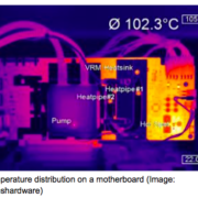
So, to first access the heat sources of the fuzzy bear an infrared camera must be used. This will allow for precise determination of components generating the most heat. An example of this can be seen in the figure below in which temperature differences are seen by the color gradients from an example circuit board .
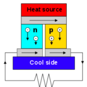
In regards to the fuzzy bear robot, I propose to use convection to cool, or transfer heat throughout the robot in order to potentially reuse the heat for another purpose. But this will rely heavily on the amount of heat the fuzzy bear’s electrical components generate in combination with the outer surface covering which will retain heat. Again, how much heat the total system will generate determines the course of action. As stated previously, the first step is to map out the bear using the infrared camera when the bear is in different scenarios such as moving, or while on for extended periods of time. So, essentially two scenarios will be possible depending on the total heat generation of the bear. The first scenario, is the electrical components including the enclosure do not generate enough heat to be reused by a proposed device such as the Seebeck or thermocouple. If this were the case, then the proposed goal would then become to efficiently cool the bear by means of convection. Essentially, circulating the air inside the bear via a micro-fan and duct system which will allow the hot air to be carried away from the hotter electrical components via convection. This hot air can then be used in one of two ways. First it can be redirected to a specific spot on the inside of the bear to create a warming effect, or it can be expelled outside through a discrete opening composed of a thinner outer material. The cooling system would then be controlled by an infrared sensor, or sensors such as the Melexis Contact-less Infrared Sensor – MLX90614 5V. An interrupt could be coded for the infrared sensor which could monitor the temperature inside the bear. If the temperature became to hot the fan would come on, or if the bear wanted to become warm for embrace then heat could be diverted via a separate duct. So possibly two ducts, one to expel the hot air and one to divert it. The cooling system could be used with deionized water, or mineral oil which is used for computer cooling. But for liquids there is always a risk of leakage, and mineral oil is expensive. Also, the components required for liquid cooling could potentially add significant weight which has already been an issue thus far in the project. The second scenario, would mean that the bear generates enough total heat to be reused by the thermocouple, so that the energy produced could perhaps recharge its batteries or power the micro-fan to cool the bear and incite the warming embrace effect of the bear. A Peltier block works by taking two good thermally conductive plates, and then sandwiching two semiconductors between them as seen in the figure below. Essentially, heat or energy travels from high potential to low potential. The plate labeled “Heat source” receives or has the high heat potential. The cool side plate has the low heat potential. The heat or electrons flow from high to low potential, but while doing so they create a voltage potential in the n and p type semiconductor materials. This occurs because the semiconductors plates are doped with different elements giving them different potentials when a current is ran through them. That potential can then be used to drive a load such as a fan or whatever is the case.
So, we can exploit this fact by strategically placing the TEG to absorb heat from the fuzzy bear electrical components, and then possibly using that energy for some other purpose. The TEGs are are lightweight have a dimension of 40mm x 40mm x 3.4mm and are cheap. So utilizing them for this project could be possible, but the temperature generation needs to be measured and taken into account.
In conclusion, I have proposed two methods of cooling either liquid or air convection. I prefer to use the air duct cooling system because of size and weight constraints, and no potential for fluid leakage. Once adequate temperature generation is measured a TEG could then be used to power the cooling fan or recharge batteries which is dependent upon the amount of heat generation. The first step again would be to measure the temperature generation using the infrared camera to verify the heat generation. Overall, this aspect of the project has the potential to make the bear more energy efficient.
Thermal Testing
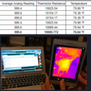
Initially a cooling system composed of ducts with either air or liquid was proposed, but after temperature test were conducted it seems that cooling was not as critical as originally thought. To substantiate that claim, 4 temperature test were conducted. The test were done with a thermistor and infrared camera. The first test conducted was a baseline test to verify that the thermistor and infrared camera were measuring the same temperature. So, in fig. 3 you can see the temperature of the thermistor being measured by the infrared camera. Then also in the same figure you can see the thermistor values being read and displayed via the serial monitor window. The results showed that the average thermistor value was 76.4 degrees while the infrared camera read 76.7 degrees verifying that both devices were measuring the same temperature.The second test conducted was a mock
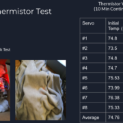
test of a bear skin which was to determine how hot the fuzzy bear’s servo temperatures reached. Fuzzy bear was placed on an elevated stand in order to walk in place. Then placed in a box filled with stuffing from a bear. The box was then covered with a blanket to simulate the effect of the bear skin. The 8 servos of the fuzzy bear, had their initial temperature measured. Then fuzzy bear walked for 10 mins continuously, and then the servos temperature was taken again. The results are listed in fig. 4 which show that the highest final temperature taken was 84.62 degrees Fahrenheit. The 3rd temperature
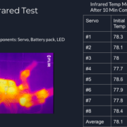
test conducted involved measuring the servo temperatures using the infrared camera. Fuzzy bear was programmed to walk continuously for 10 mins. The Initial temperatures of the 8 servos were taken before walking, and the final temperatures were taken after. According to the temperature measurements in fig.5 table the highest servo temperature reached was 91.2 degrees Fahrenheit. The final temperature test was conducted using the internal temperature sensor for the Atmega32u4, and the infrared camera.
The results showed that neither the internal temperature sensor, nor the infrared camera temperature measurement reached above 85 degrees Fahrenheit. The temperatures were taken in the same manner as the previous results with an initial measurement before the fuzzy bear walked, and then after fuzzy bear had walked continuously for 10 mins. According to the Atmega 32u4 data sheet the max operating temperature is 180 degrees Fahrenheit. The servo MG90 used for the fuzzy bear has a max operating temperature of 130 degrees Fahrenheit. So, it seems that according to temperatures measurements, the 8 servos and Atmega32u4 are well within operating temperatures. A question that my be posed from the results could be how come the continuous walking temperature measurements for the thermistor and infrared camera differ so much? In fact, there averages differ by 8.76 degrees Fahrenheit. This seems due to the fact that when using the infrared camera, one can clearly see the hottest part of the measured component. While locating the hottest part of the measured component using the thermistor is much more difficult. Also, it seems that the servos outer covering seems to prevent the thermistor from getting very close to desired proximity for accurate temperature measurement. So, overall the infrared camera seems sufficient enough to accurately measure the electrical components temperature, and this was validated by the baseline test. Also, a thermometer temperature, thermistor temperature, and infrared camera temperature was compared, and each was within 1 degree of one another in Fahrenheit. Finally, the last topic of interest regarding the fuzzy bear is the heating capability of the fuzzy bear skin.
Conclusion and FuzzyBear Warming Function
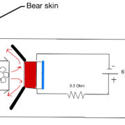
Essentially, the bear will be heated by a Peltier block whose function was previously discussed in this post. The Peltier block becomes hot on one side (indicated by the red color Fig.6) while the other side becomes cool(indicated by the blue color Fig.6) this occurs when a voltage is applied across its terminals. So, the plan is to mount the cool side to the underside of the bear and have the hot side facing towards the belly of the bear skin. Then the Peltier block will have a 5v blower that uses convection, and ducts to cause hot air to flow from the hot side of the Peltier block to the belly of fuzzy bear. The Peltier block has been tested, and can draw high current, so a 3.3 ohm resistor is necessary to limit the current to 500 mA. The power for the Peltier block will come from the 6 volt battery pack. The power for the 5v blower will come from the 3 dot board. The Goal is to heat the bear skin to 85 degrees Fahrenheit which seems to be achievable due to the amount of heat the Peltier block can generate with the given power constraints.

