Screw-Driver/Spring/2019
Trade Off Studies: Design of Driving Screws
Author/s: Christian Pla, D&M
Introduction
During the mechanical design of our robot, we realized that some compromises had to be made concerning the features of its individual components in order to fulfill its constraints and mission profile. The design of the driving screws, for example, has significant influence on the overall speed and traction of the robot. Also, we had to consider trade offs during our selection of the motors as well. The specifications of the motors and the geometric features of the driving screws, therefore, will be the deciding factors of the traction, torque, and speed of the robot.
Driving Screws: Pitch vs. Thread Rotation Count
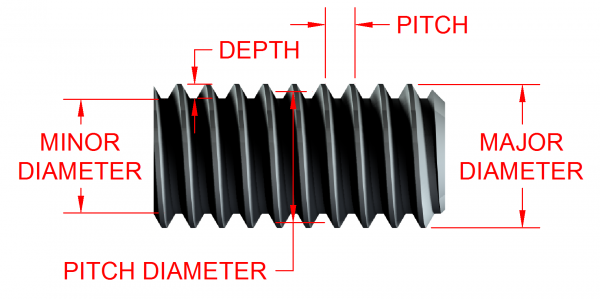
In another one of our blog posts, entitled “Screw-Driver Speed and Torque Calculations”, we deduced that that the forward (or backward) speed of the the robot will be proportional to the pitch of the driving screws. For our rapid prototype, therefore, we hastily designed the screws to allow for largest reasonable pitch possible. Intuitively, however, you may tell that if you have a a screw of a constant length, the larger the pitch is made, the smaller the thread count. See fig. 1 for screw dimension terminology.
figure 1. Standard nomenclature of screw dimensions. Taken from: https://www.philholdenfasteners.co.uk/evolution-screw-threads/
During testing of our prototype, we realized that although we had the largest reasonably allowed forward/backward speed given that we had designed the screws with the largest reasonably allowed pitch of 2 inches, we noticed that the robot had some trouble with traction through the substrate it was traversing through. We realized that this had to do with the the “rotation count” or number of full rotations of the threads about the cylinder of the screw.
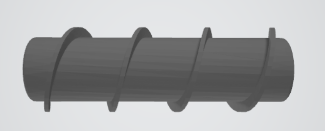
For our rapid prototype, the pitch of the screws is 2 inches, however the rotation count of the threads is only 3. See figure 2. And we can easily conceptualize that the more rotations on the screw, the more fine substrate can be pushed away from the robot. According to Newtons Third Law, this allows for greater propulsion ability through the substrate. A higher rotation count can therefore allow for greater traction.
Figure 2
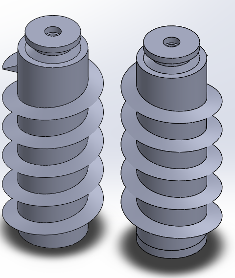
For the final design, therefore, we sacrificed pitch for a higher rotation count. Our final design is far smaller than the rapid prototype, so were hesitant to decrease the pitch and therefore decrease the forward/backward speed of the robot any further. We, however, knew that traction ability through the medium is critically important as the maximization of this speed is pointless if the robot cannot easily drive itself through the substrate. For the smaller screws (3.4 inches in length and 1.5 inches in total diameter) of the final design, we therefore settled on a pitch of 0.5 inches for a higher rotation count of 6. See Figure 3
Figure 3
DC Motors: Speed vs Torque
Lastly for the final design, we were required to have smaller motors proportional to its size. In order to ensure that the robot does not stall under normal environmental conditions, the consistency of the substrate in particular, we wanted smaller motors with highest possible stall torque. For the motors we therefore settled on motors of higher torque for less angular speed. These motors are rated at 6V @ 155 rpm.
Conclusion
Based on what we learned from testing the rapid prototype, we conducted trade off studies to ensure that the robot can perform its main purpose of driving through off-road terrain, or rather loose substrate. For the final design, therefore, we had to sacrifice speed for better torque and traction.
References/Resources
1. Image was taken from the following website: https://www.philholdenfasteners.co.uk/evolution-screw-threads/


