Trade-Off Study: PCB Form Factor
By Eric Hanna (Design and Manufacturing)
I examine the pros and cons of Fall 2015’s PCB form factor versus the PC/104 standard.
Table of Contents
Introduction
In order to decide the specific form factor for our board, a tradeoff study was done to compare the standardized form of the PC/104 standard versus Fall 2015’s blank PCB board. In the trade-off study we will attempt to determine which form factor will work better or possibly determine that a combination of the two will be required to meet our requirements. The main requirement is the size of the board, which has to fit in our cube satellite (cubesat) chassis.
PC/104 Form Factor
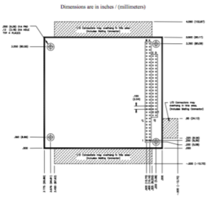
PC/104 is often referred to as a “stackable PC,” because multiple PC/104 boards are stacked on each other to make a complete PC. The PC/104 form factor also has a complete set of requirements / specifications (they can be found here) [1].
The specifications include: board area, component overhang and height limitations, mounting hole size/location, bus connector size and pin specifications, etc.
Fall 2015’s PCB Form Factor
The design of Fall 2015’s blank PCB board was found in their folder of SolidWorks models. Their PCB’s dimensions were dependent on the chassis they designed based on the Innovative Solutions in Space’s chassis design. Other than the basic area and hole size and placement, the previous semester’s design doesn’t have other requirements specified. Because the board was designed in conjunction with the design of the chassis, the basic dimensions of the board should be used.
That is, because the chassis and mounting systems are already made, we must use at minimum the mounting hole locations from Fall 2015.
Conclusion
Before performing the trade-off study, Fall 2015’s blank board dimensions are the obvious choice – it was designed in conjunction with the chassis and therefore fits inside of it. The Fall 2015 board only defines basic dimensions. Therefore features from the PC/104 form factor will be combined with the dimensions of the Fall 2015 board for our design.
Trade-Off Study
| Requirement | PC/104 |
Fall 2015 |
| The board shall fit within the chassis. (area constraint) |
90 x 96 mm area | 89 x 92 mm area |
| The maximum component height shall not exceed that of the cube unit. | 11.05 mm max. component height |
n/a |
| Mounting hole locations must match those of Fall 2015’s board. |
Do not match (see Figure 2) | Match |
| Mounting holes should be 3.4 mm in diameter. |
3.18 mm diameter |
3.4 mm diameter |
| All electronics on the PCB shall be mounted in place and grounded to the satellite chassis to prevent charge accumulation. | PC/104 Form Factor’s Stackable Bus Connector specifies 4 pins reserved for ground. | n/a |
| The form factor of the board should allow it to be stackable and connect with other boards inside the satellite payload. |
The PC/104 Form Factor features a 64-pin Stackable Bus Connector, allowing it to fulfill this requirement. |
n/a |


