3Dot Troubleshooting & Bootloader Burning
Table of Contents
3Dot Troubleshooting
Error Codes
When there is an error in a command sent to the Arduino/3DoT, a telemetry packet with an Exception Code will be returned. Below is a list of the possible Command Exception codes. Following that, an example showing how to read exception code telemetry is provided.
Command Exception Codes
The finite state machine for command processing and decoding will generate the exception or error codes listed below. These codes will be sent to the Arduino IDE “Serial Monitor” as well as telemetry to the ArxRobot App.
01 Start byte 0xA5 expected
02 Packet length out of range 1 – 20
03 LRC checksum error
04 Undefined command decoder FSM state
05 Array out of range i >= 23
Exception Code Example
In this example, the camera home command is sent with an incorrect LRC byte to examine how exception codes work.
A5 01 04 00
Command Packet ID = A5
Packet Length N = 01
Camera Home = 04
Parity = 00 A0 = A5 ⊕ 01 ⊕ 04
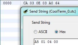
The telemetry packet (CA…) in Figure 12.1 was sent as a response from the 3DoT board when the command packet (A5 01 04 00 above) was sent. Looking at the command packet (start byte = A5), the user has sent a CAMERA_MOVE_HOME (3rd byte = 04) command with the LRC byte as 00. By calculating the LRC byte by hand (A5 ⊕ 01 ⊕ 04) it is shown that the correct LRC byte is equal to A0.
The 3DoT firmware responds to this simulated data transmission error by sending telemetry packet CA 03 0E 03 A0 64 as shown in Figure 17-1.
Figure 17-1: Telemetry packet sent from Arduino/3Dot board.
| data[i] | i = 0 | i = 1 | i = 2 | i = 3 | i = 4 | i = 5 |
| Packet | CA | 03 | 0E | 03 | A0 | 64 |
| Description | Packet ID | Packet Length N+1 | Command Exception ID | LRC Checksum Error | Expected Checksum | Packet Checksum |
The “Telemetry ID” is 0E, which is sent indicating an error was detected when trying to decode the command. 03 indicates that LRC byte sent is incorrect. In this example, A0 is the expected LRC byte that is needed to be sent. Knowing this, if the user were to send the exact same command packet, but changing the LRC byte to A0 (A5 01 04 A0), the microcontroller will not reply with a telemetry packet again.
Going back to the telemetry packet (start byte = CA), the last byte is now the LRC byte for the telemetry packet (CA ⊕ 03 ⊕ 0E ⊕ A0 = 64). Again, this component is used to verify that all elements were read accurately.
It is not important understanding how to find the LRC bytes for telemetry packets, as they are automatically calculated, but it is good to know the purpose of the LRC byte for data packets for both commands and telemetry and how it is computed by the software.
Bluetooth Troubleshooting
Connecting over Bluetooth can be finicky at times. If there are too many nearby sources try initially pairing to the 3Dot on your own (in isolation). If connecting still doesn’t work: first try restarting the 3Dot and rescanning Bluetooth within the app. If connecting proves to not work consistently try these steps:
- Turn off 3Dot
- Force Close Arxterra
- Turn off and on Bluetooth (in phone settings)
- Reopen Arxterra
- Then scan for devices within Arxterra
Burning Bootloader and Fuse Settings
A bootloader is the first piece of code a microcontroller executes when it is powered ON. Usually, manufacturers burn the appropriate bootloaders into microcontroller chips prior to selling them. For instance, this is how computers recognize the type of Arduino plugged into it. However, dealing with a fresh microprocessor chip, the bootloader will have to be burned onto it before it is capable of being programmed. This tutorial will walk through how set the appropriate fuse settings and burn the 3DoT Bootloader to the board.
Equipment
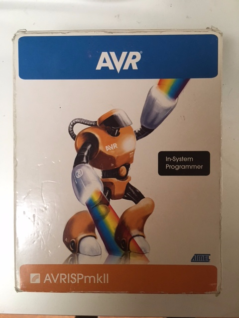
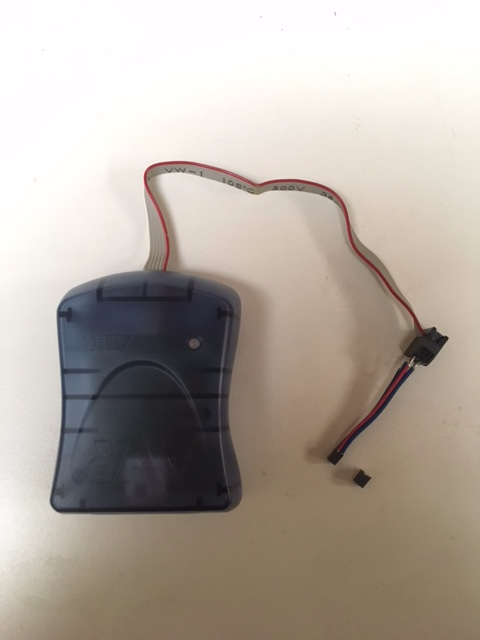
- AVRISP mkII compatible USB programmer
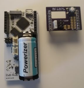
- 3DoT ICSP breakout
- 3DoT Board
- A PC with Atmel Studio 7 installed*
* Or any computer with AVRDude usable through a command line interface (advanced).
Connecting the 3DoT Board
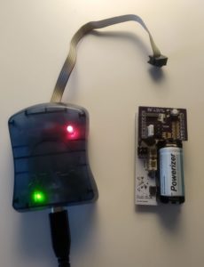
STEP 1: Connect the AVRISPmkII to your computer. If the internal LED turns green suitable drivers are detected. If not, see “Installing MKII Driver” below.
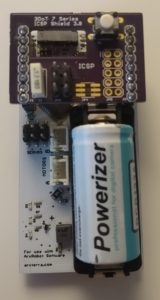
STEP 2: Connect the 3DoT ICSP breakout to the 3DoT as shown.
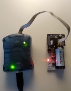
STEP 3: Connect the AVRISPmkII to the breakout board. Ensure the ribbon cable is oriented to have the red wire closest to the switch and USB port.
STEP 4: Insert a battery and turn the board ON.
The external LED will light up green when the board is detected.
Installing MKII driver
If the AVR programmer is not recognized by your computer, the appropriate driver must first be installed. Download the proper driver for the AVR programmer from the web. If the AVRISP MKII driver is being used, it can be downloaded from this link. If the USBtiny AVR Programmer is being used, the driver can be downloaded from this link.
To configure AVRISP MKII Programmer to work with Arduino IDE (steps to download in section “02 – 1: Arduino IDE Tutorial”), it is necessary to install lib-win32 drivers. Extract the downloaded zip file, then follow the steps below to install AVRISP drivers:
STEP 1: Disable windows driver signature enforcement by following steps in this tutorial.
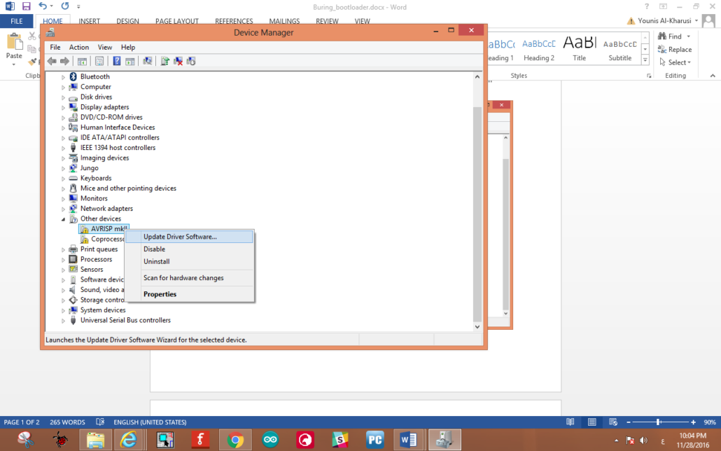
STEP 2: Plug in the programmer to computer intended for the installation process, then open the “Device Manager”.
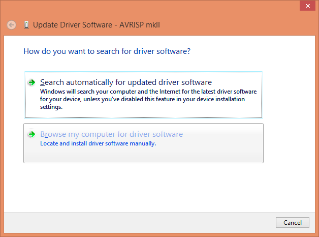
STEP 3: Right-click on “AVRISP mkII” and click on “Update Driver Software”.
STEP 4: Click on “Browse my computer for driver software”.
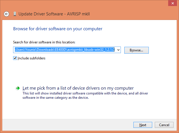
STEP 5: Make sure that “Include subfolders” is checked, then click on “Browse”.
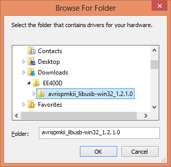
STEP 6: Navigate to the extracted folder (i.e. avrispmkii_libusb-win32_1.2.1.0), then click “OK”.
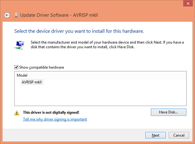
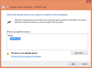
STEP 7: Click on “Let me pick from a list of device drivers on my computer”.
STEP 8: Click on “libusb-win32 devices”.
STEP 10: Click on “Browse” and locate “AVRISP_mkII.inf” in the “Downloads” folder.
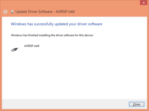
STEP 11: Click “Next” to close and the driver should be successfully installed.
Writing the Fuse Settings
Now, setting the correct fuse settings can be done by two methods:
Method 1: Using Atmel Studio 7 (Windows Only)
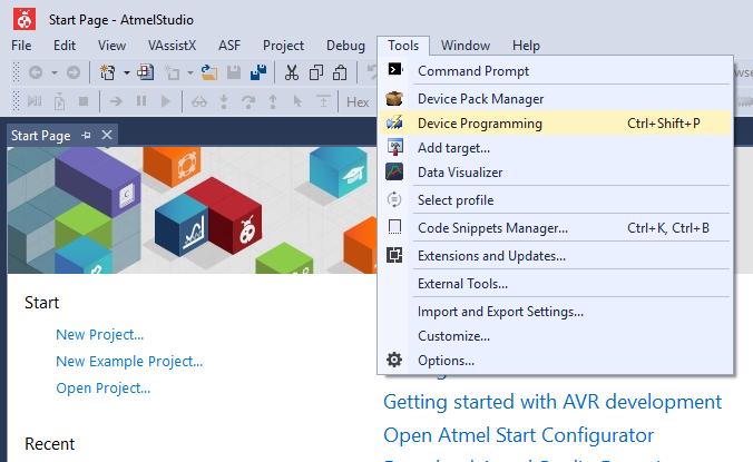
STEP 1: Open Atmel Studio 7 and click Tools -> Device Programming.
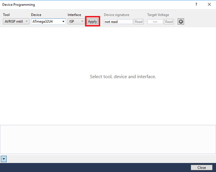
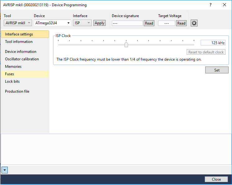
STEP 2: The following window will appear. The tool to select is the AVRISPmkII. The device to select depends on what microcontroller is being used on your device. In the case of the 3DoT board, you will be selecting the Atmega32U4. You can find it by using the drop down menu or by typing out the name. Ensure the settings are as pictured and click “Apply”.
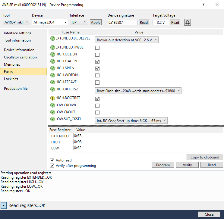
STEP 3: If your device connected successfully you should see the following window. Click “Fuses”.
STEP 4: Set the fuses as follows:
Extended Fuse: 0xCF
High fuse: 0xD8
Low fuse: 0xE2
and click “Program”. To understand what each fuse setting does, refer to the ATmega32u4 Datasheet.
A warning may pop up to change to certain fuses. These warnings can be accepted.
Method 2: Using avrdude (All platforms)
STEP 1: Download and install WinAVR.
( On Linux run sudo apt-get install avr-libc avrdude binutils-avr gcc-avr srecord )
( On OS X install CrossPack and libusb)
STEP 2: Open Command Prompt (or a terminal window on Linux/OS X). Paste the following command into the command prompt.
avrdude -c avrispmkII -p m32u4 -P usb -U efuse:w:0xCF:m -U hfuse:w:0xD8:m -U lfuse:w:0xE2:m
This will configure the fuses to the setting best suited for the 3DoT board.
To customize the fuse settings, see this calculator for the possible options.
Burn Bootloader using Arduino IDE
STEP 1: Plug in the ICSP socket to the 3DoT board and jumper wires to the proper AVRISP mkII programmer pins. Then switch ON the 3DoT.
STEP 2: After switching the 3DoT ON, the LED on the AVRISP mkII programmer will change from red to yellow.
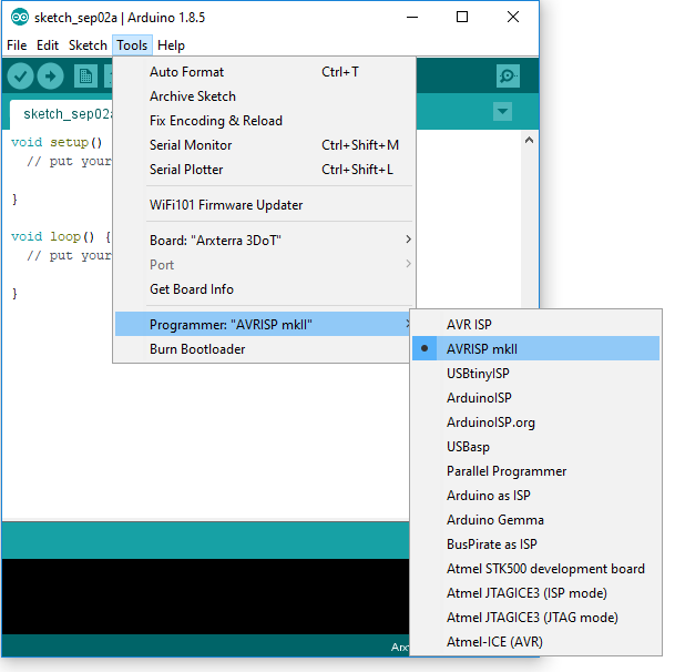
STEP 3: Open Arduino IDE and go to Tools > Programmer. Make sure “AVR mkII” is selected.
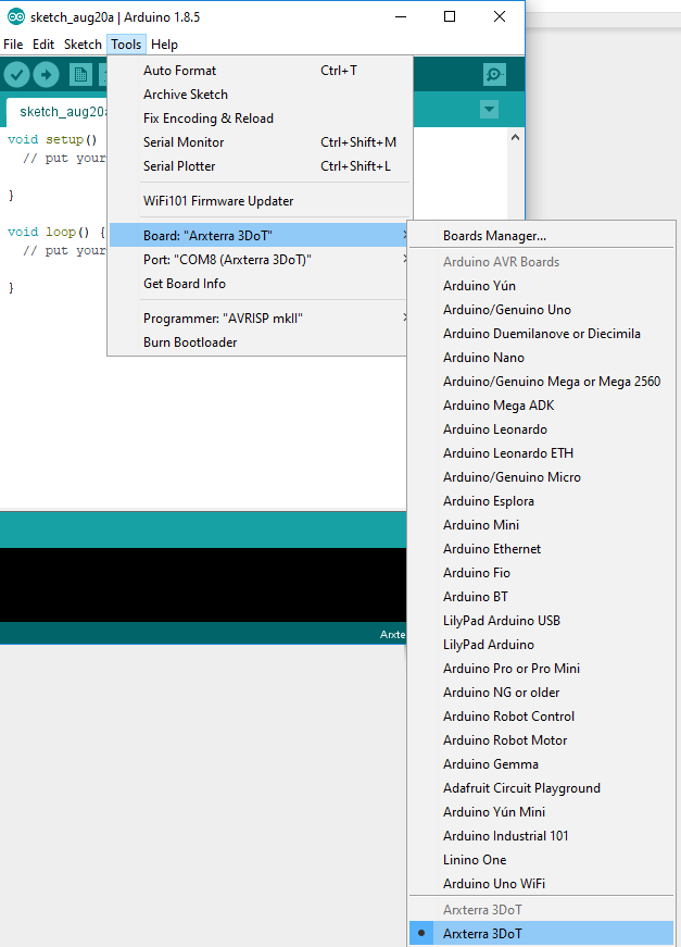
STEP 4: Select “Arxterra 3DoT” from Tools > Board.
If the Arxterra 3DoT board is not installed in your Arduino IDE, see the “Arduino IDE 3DoT Tutorial”
STEP 5: Go to Tools > Burn Bootloader.
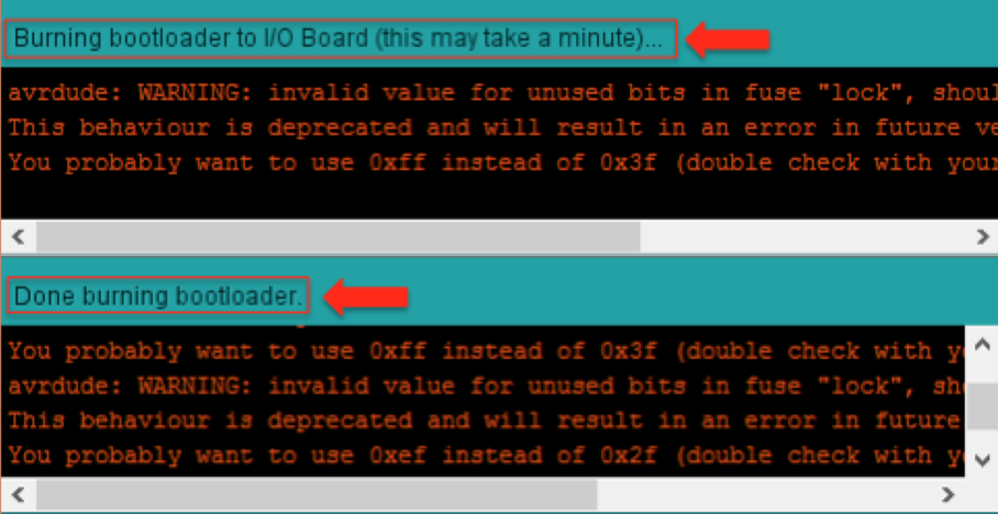
STEP 6: Ignore the “WARNING” and wait for the Bootloader to be burned.

