UFO Spring 2016 – EDF Area Coverage With Flap Length Calculations
Written and posted by: Luis Valdivia (Project Manager)
Table of contents:
Introduction
Approach
Formulas
Conclusion
Possible Solution
Introduction:
When attempting to angle the thrust coming from the Electric Ducted Fan (EDF), there is a risk of covering the ducted fan area to prevent vertical flight. This post will explain our research done to determine the maximum area allowed to control the aircraft without losing vertical thrust.
Approach:
Using middle school math, we can figure out the area of the flap size and the area of the duct.
Figure 1.1 demonstrates the area of the duct being covered by the flap, along with formulas for area.
Because of the size of the EDFs, we will assume the length of the flap is fixed at 55mm. The Width of the flap will depend on the area of the opened duct, aka the area of the circle. For a fully opened duct (meaning no coverage of the circle) we can produce a maximum thrust of 650g with a flap of length 0mm. With a partially opened duct (meaning half of the circle is covered) we can produce half the thrust of 324.99g with a flap length of 27.5mm. Finally, for a fully closed fan duct we will produce 0g of thrust with a flap of length 55mm.
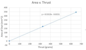
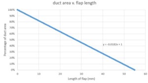
Inputting our 3 sets of values into excel, we can fit a linear line into our data plot to obtain the equation of our line. This equation will help us calculate more values to get a better understanding of the range between flap length and available output thrust.
Figure 1.2 Linear fit plot of Duct Area vs. Thrust (with equation of line)
Figure 1.3 Linear fit plot of Duct Area vs. Flap Length (with equation of line)
Formulas
Area of duct = 2*π*(radius*percentage of opened duct)
Length of flap = 55mm(100 – percentage of opened duct)
Area of flap = length of flap * 55mm
| Thrust (g) | Area of duct | Length (mm) | area of flap (mm^2) | % of open fan |
| 650 | 345.4 | 0 | 0 | 100.00% |
| 643.48137 | 341.946 | 0.55 | 30.25 | 99.00% |
| 636.9815581 | 338.492 | 1.1 | 60.5 | 98.00% |
| 630.4817463 | 335.038 | 1.65 | 90.75 | 97.00% |
| 623.9819345 | 331.584 | 2.2 | 121 | 96.00% |
| 617.4821227 | 328.13 | 2.75 | 151.25 | 95.00% |
| 610.9823109 | 324.676 | 3.3 | 181.5 | 94.00% |
| 604.4824991 | 321.222 | 3.85 | 211.75 | 93.00% |
| 597.9826872 | 317.768 | 4.4 | 242 | 92.00% |
| 591.4828754 | 314.314 | 4.95 | 272.25 | 91.00% |
| 584.9830636 | 310.86 | 5.5 | 302.5 | 90.00% |
Conclusion:
As you can see, the thrust output from the EDFs will beginning to decrease if we cover the duct. Although, from a previous blog post we mentioned the necessary thrust to lift the weight of the aircraft. The necessary thrust to lift a quadcopter weighing in at 1291g is 645.5g thrust for each EDF. From our table above, it seems like covering the duct at anything greater than 0.55mm will prevent our UFO from lifting off the ground.
Possible solution:
In order to continue the project with thrust vectoring, the EDFs will have to be swapped with fans of thrust greater than 650g. Another solution is to reduce as much weight as possible to lift the UFO and vector the thrust we a reasonably sized flap.


