Goliath Fall 2016
Updated System Design
By: Diana Nguyen (Missions, Systems, and Test Engineer)
Approved by Kristen Oduca (Project Manager)
Table of Contents
System Block Diagram
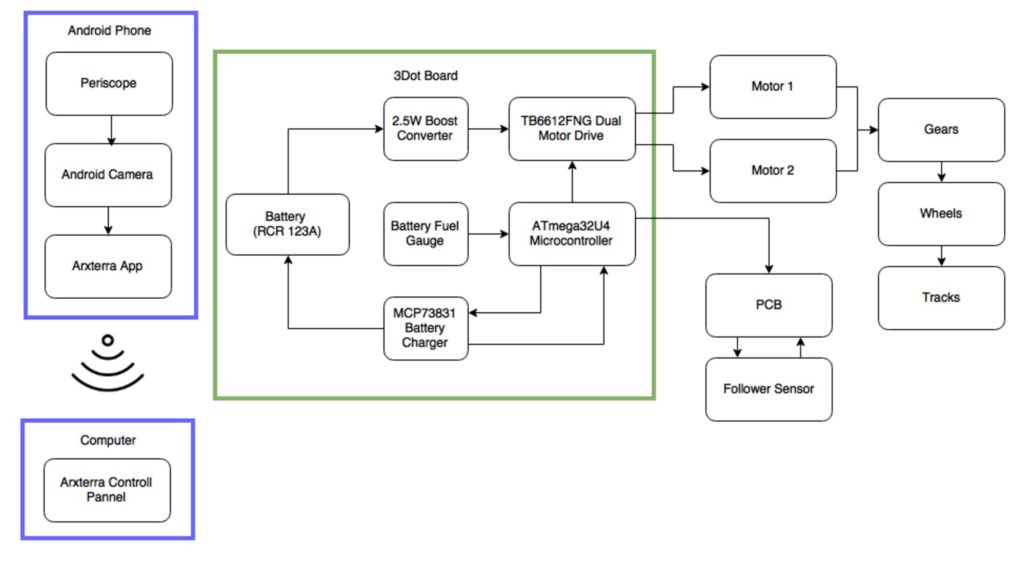
The system block diagram illustrates how the different components of each system interact with each other. From the Diagram as shown in Figure 1 you can see that our phone and computer are a separate system from the 3Dot board since they are not necessary have the Goliath to be autonomous. The phone system is a periscope connected to the phone’s camera while it is on producing a live feed on the Arxterra Control Panel.
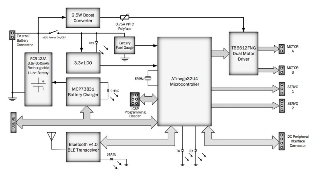
Figure 2 is the block diagram of the 3Dot board that we will be using.
However, if you look at the block diagram you can see our 3Dot board block is different. That is because we did not use all the components of the 3Dot therefore only the components that we will be using are included on our system block diagram. One of the main things component we did not use was the Bluetooth v4.0 BLE Transceiver since we will not be operating in remote control (RC) mode.
Software Design
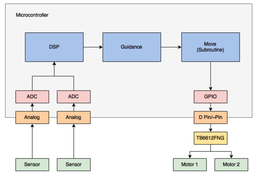
The software design is a project document that illustrates the the inputs and outputs intact with the microcontroller. As stated in the previous section, our 3Dot board does not have a bluetooth module since we will be autonomous and do not need to use RC mode. Because we don’t have a bluetooth module Goliath can not send telemetry. In addition, we are going to be an autonomous vehicle. This means we will not be sending commands to the robot.
Goliath has two input, the two following sensors, which are analog and need to be converted to digital. This is shown in Figure 3, Goliath’s software block diagram.
In the guidance block we will be looking at two aspect, how far away the Biped and what location of the Biped from Goliath. From this we can calculate the speed and direction that the Goliath needs to go. With this information we can determine the speed we need to turn for each motor.
Interface Definition Design
The interface definition design is used to map out all the pins of the components of Goliath as shown in Figure 4. The components we pinned out are the motor driver, LiPo charger and follower sensor.
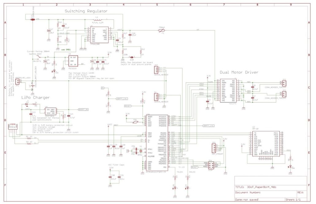
We can find out where these pins are from the ATmega 32u4 to the different components and and how they are connected from the 3Dot board schematic as shown in Figure 5. The only connections that are not made on the 3Dot board would be the connections for the following sensor.
Resource Report
The resource report looks at our allocated budget, mass, and power for our project. This helps us plan and estimate what we may be looking at if we go through with our project.
Budget Report
The resource report looks at our allocated budget, mass, and power for our project. This helps us plan and estimate what we may be looking at if we go through with our project.
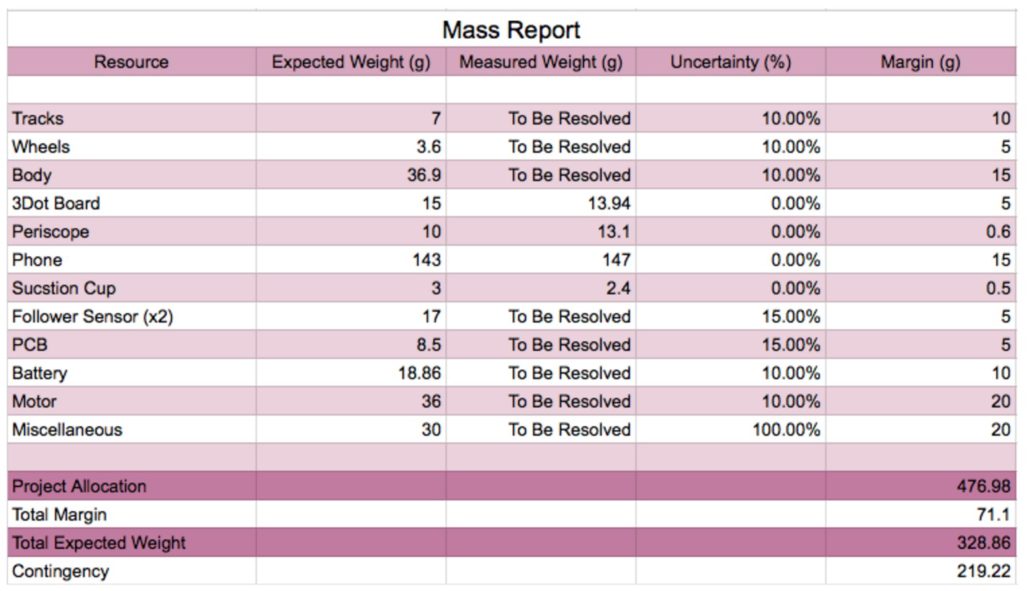
Mass Report
The mass report looks at the potential components that will be contributing to the Goliath’s weight when it is active. We have access to some of the components and have actual measured values to them as shown in chart in Figure 7.
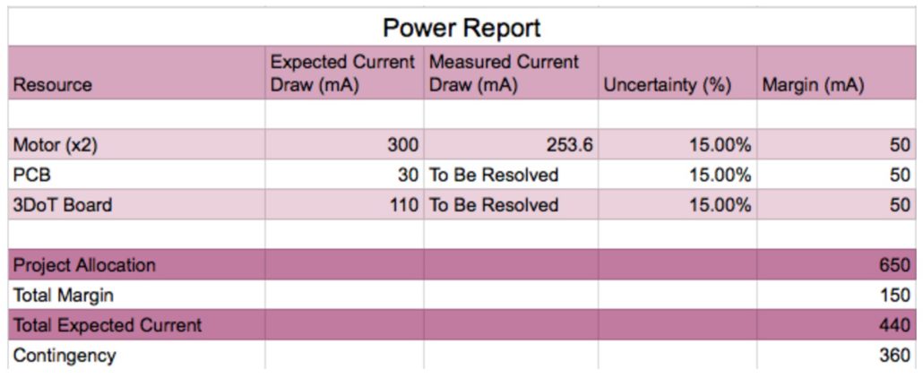
Resource Report
Lastly, the power report looks at how much current our project potentially has and how much the current components will be taking up as shown in the chart in Figure 8. The project allocation for power comes from the rating of the 3.6v 650mAh Li-Ion battery that we will be using to power the 3Dot board.

