Published By: Luis Valdivia (Project Manager)
Written By : Luis Valdivia (Project Manager)
Table of contents
Intro
PWM Method
Example Sketch using potentiometer
Example sketch without
Controlling servo without PWM
Intro
Controlling servo motors on an Arduino Uno can be easily done with the provided pins. However, what happens when you run out of PWM pins? The Arduino website says you can control up to 12 servo motors on the arduino uno, even though the Uno only provides 6 PWM pins. For our UFO quadcopter we plan on achieving stable flight by vectoring our thrust with the help of servos. Since we have 4 Electric Ducted Fans that need to vector thrust in both the X and Y direction, we will need 8 servo motors. We can control 6 servos using PWM pins and the remaining 2 will be controlled with non PWM pins. Keep in mind, this is just a demonstration on how we are testing our servos. For our final control of the servos, we will be using a PCB with a servo driver implemented on the board.
PWM Method
Using the Pulse Width Modulation (PWM) method, we can use the servo library provided by arduino to easily control our servo motor. The arduino website provides two useful example sketches to help you with servo control using the PWM method.
Example sketch using potentiometer
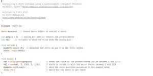
This sketch allows the user control of a servo using a potentiometer. You can view the code below for explanation. If you would like to see the schematic explained, click here to access the arduino. This sketch can be very useful for testing servos. By including the Serial.println(val) line, we can monitor the position of the servo and see the maximum angle the servo can reach. This will come in handy when we code our servos, we can set the exact value and prevent the servos from over turning and damaging the plastic gears.
<i></i>
Make sure the USB cable is still plugged in to the arduino and computer to display measurement angles. Afterwards, you click on the magnifying glass on the top of the sketch window, then select the baud rate (9600)
Example sketch without potentiometer
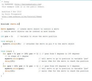
This method deals without the use of a potentiometer to control the servos. Basically, a loop will run and decrease the position of the servo everytime the loop iterates. The wiring on this example isnt too difficult, but I recommend clicking on this link to read what arduino has to say.
Controlling a servo without a PWM pin
For most projects I would highly recommend using the PWM pins or using a Servo driver that supports PWM pins like this one . Although, this method adds less hardware, cheaper (FREE!) and instant ( no shipping or handling required). FOR THE FINAL ASSEMBLY OF THE UFO QUADCOPTER WE PLAN ON USING A SERVO DRIVER SIMILAR TO ADAFRUITS, ON OUR PCB. THIS IS JUST FOR TESTING PURPOSES.
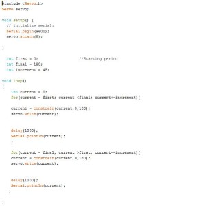
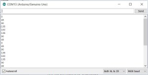
The code below will allow our servo to start and stop at a position set by the user. In my case, I want to start at 0° and finish at 180° with increments of 45°. If you click the magnifying glass like in the previous examples, you can see the position of your servo.
<span style="font-weight: 400;"> </span>
Here is a screenshot of the serial monitor:
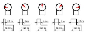
Here is an explanation how the servo library controls your servo. The library employs the sending of periods (ms) to the servo circuitry. Using the picture below from, letsmakerobots.com , this method can be better explained.
As you can see, the servo only travels from 0 to 180 degrees.
0° → .5 ms
45° → 1 ms
90° → 1.5 ms
135° → 2 ms
180° → 2.5 ms
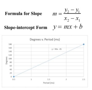
Since these results are linear, we can do some back of the envelope calculations to figure out the degrees per period conversion and vice versa.
After plotting 2 points on Excel, we can determine the linear trendline to determine our conversions. Below are the conversion formula(s) you will want to use to determine the position of your servo motor.
Degree = (90* Period) -45
Period = (Degree +45) / 90


