Viewing Command and Telemetry Packets
Table of Contents
Packet command and telemetry channel data may be viewed directly in the ArxRobot App or using a terminal application program like CoolTerm. It should be noted that Atmel Studio 7 has a built-in telemetry window. The former is the subject of this chapter.
Trace Commands to the 3DoT Microcontroller Unit (MCU)
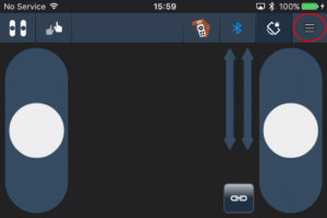
Step 1: To reveal trace statements of the major commands and telemetry messages that are being processed, open the Action Bar tray by selecting the hamburger icon “≡” on the right of the icon menu bar as shown in Figure 13.1.
Figure 13.1: How to open the Action Bar tray.
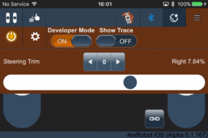
Step 2: When the Action Tray opens, you will see a slide switch labeled “Developer Mode.” As shown in Figure 13.2, sliding this switch to the ON position, will enable diagnostic and configuration features of interest to programmers and hardware engineers.
Figure 13.1: Action Bar tray with developer mode turned ON.
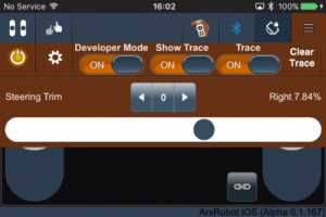
Step 3: To reveal trace statements activate the switches for “Show Trace” and “Trace”.
Figure 13.2: Action Bar tray in developer mode, with “show trace” and “trace” turned ON.
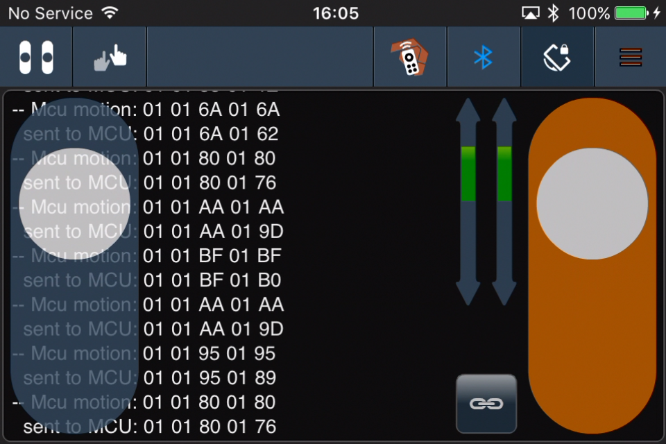
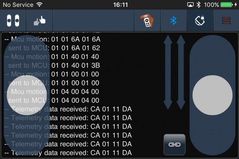
For example, note the statements appearing as the motor controls are moved as shown in Figure 13.3.
Figure 13.2: Trace as motor control sliders are moved.
After a quick review of Section “Command Packet Example – Move Forward at Half Speed”, we see that after each line starting with “sent to MCU” are bytes i = 2 to 6 of a command packet.
| data[i] | i = 0 | i = 1 | i = 2 | i = 3 | i = 4 | i = 5 | i = 6 | i = 7 |
| Packet | A5 | 05 | 01 | 01 | 6A | 01 | 6A | A1 |
data [0] = Command Packet ID
data [1] = Packet length w/o parity byte (N = 05)
data [2] = Command ID = Move
data [3] = Left Motor Forward
data [4] = Half speed (128/255)
data [5] = Right Motor Forward
data [6] = Half speed (128/255)
data [7] = LRC byte
Trace Telemetry from the 3DoT Microcontroller Unit (MCU)
|
WARNING The “Trace” setting should not be kept ON indefinitely, because it can drastically slow the app’s performance. |
Step 1: If you want to see hexadecimal string representations of all bytes arriving from the MCU, open the settings (“cog” icon) menu and select the “Components Test Configuration” view.
Figure 13.3: Open the test configuration window.
Figure 13.4: Trace raw data incoming from MCU slide switch to ON.
You should now see telemetry from the MCU as shown in Figure 13.5.
Figure 13.5: Trace of MCU telemetry.
After a quick review of Section “12 – 4: Telemetry Packet Example – Move Forward at Half Speed”, we see that after each line starting with “sent to MCU” are bytes i = 2 to 6 of a command packet.
After a quick review of Figure 12.6: Telemetry IDs and Section “12 – 3: Command Packet Example – Command Exception Code”, we see that after each line starting with “Telemetry data received:” is a telemetry.
| data[i] | i = 0 | i = 1 | i = 2 | i = 3 |
| Packet | CA | 01 | 11 | DA |
data [0] = Telemetry Packet ID
data [1] = Packet length w/o parity byte (N = 1)
data [2] = Telemetry ID = Pong
data [3] = LRC
A Pong packet is sent by the MCU in response to a Ping command from the processor (see Arduino libraries Robot3DoTBoard src TelecomClass.cpp). This handshake between the ArxRobot application and the MCU ensures that communications has not been lost.
Echo Command Packets
|
WARNING The “ECHO_COMMANDS” settings should not be kept at TRUE indefinitely, because it drastically slows the MCU performance and may result in loss-of-signal and other unexpected problems. |
Follow these steps to have the Microcontroller Unit (MCU) echo back every command it receives from the ArxRobot application.
Step 1: Open the Config.h file located in the Robot3DoTBoard source folder (Arduino libraries Robot3DoTBoard src Config.h) and locate the “Debug Mode” block.
Step 2: To have the Microcontroller Unit (MCU) echo back every command it receives from the ArxRobot app, make the following change to the Debug Mode, #define preprocessor directive (also known as a macro definition)..
#define ECHO_COMMANDS FALSE ⇢ #define ECHO_COMMANDS TRUE
USB Serial Communications
Previously in “Viewing Arxterra Bluetooth Wireless Communication” we looked at how to trace commands and telemetry from the ArxRobot Application. In Section “3DoT Application Development” we are going to look at how to write Arduino Scripts for your robot. While using the trace mode from the ArxRobot application will be sufficient in many cases, as the complexity of your robot increases you may want to test and debug your robot independent of the ArxRobot application. To understand how this is done we need to look at the two serial communication methods supported by 3DoT robots.
Bluetooth Communications
As demonstrated in the previous chapters, the 3DoT MCU communicates to the ArxRobot application through a Bluetooth module which interfaces on the 3DoT board to a USART peripheral subsystem on the ATmega32U4 microcontroller. Within the Arduino language this interface is the responsibility of the “Serial1” (Phone ⇄ Bluetooth ⇄ USART) object. All Bluetooth serial communication uses command and telemetry packets.
USB Communications
Although you may not have thought about it, when you write an Arduino script and upload it to the 3DoT board, you are communicating to the PC through a USB interface. Communications across the USB interface is the responsibility of the “Serial” (PC ⇄ USB) object and the data which goes across it may take many forms.
- A “.hex” file format is used to upload programs to the MCU when you press the upload button.

- Arduino instruction Serial.println(“Hello World”) sends a string of ascii characters to the “Serial Monitor” which displays this text message.
- Serial terminal programs like CoolTerm may be used to send and display packets, a series of bytes displayed in hexadecimal.
MCU Monitoring using the Arduino IDE Serial Monitor
If you have done any Arduino programming you are probably already familiar with the “Serial.print” instruction. Print instructions are the simplest way to debug your Arduino programs.
The 3DoT board also has a large number of Print instructions which are used to display status and error information during development. Follow these steps to enable these built-in “Serial.print” instructions.
Step 1: Open the Config.h file located in the Robot3DoTBoard source folder (Arduino libraries Robot3DoTBoard src Config.h) and locate the “Debug Mode” block.
Serial Terminal Programs – CoolTerm
Up to this point commands and telemetry packets have been sent and received by the ArxRobot application. As you develop and debug your robot, you will ultimately want to directly communicate to your program from a serial terminal program, like CoolTerm. This USB serial communication path is shared with the Arduino IDE (program upload and the serial monitor window). It is important to note, that all these communication paths are to a limited extent mutually exclusive. For example, an ASCII text string, like “Hello World” will appear as gibberish when displayed as hexadecimal digits in a serial monitor application. Consequently, you may want to set the DEBUG flag to FALSE when sending and receiving telemetry packets.
In the next section, we will reuse the Robot_3DoT_Blink to show you how to use the CoolTerm serial monitor application to send and receive data packets.
Robot_3Dot_Blink (Using Arduino + CoolTerm) Tutorial
In Section 11 – “Robot_3Dot_Blink Lab” you changed the blink frequency by adding a custom widget to the ArxRobot application. In this tutorial you are going to change the blink frequency by sending command packets from the CoolTerm serial terminal application.
|
To better understand what is happening “behind the scenes” before stepping through this tutorial, I would recommend turning ON the trace mode of the ArxRobot application as described in Section 13 – “Viewing Arxterra Bluetooth Wireless Communication.” |
Step 1: Open ![]() and Upload
and Upload ![]() your Robot_3Dot_Blink written in Section 11 – “Robot_3Dot_Blink Lab.”
your Robot_3Dot_Blink written in Section 11 – “Robot_3Dot_Blink Lab.”
Step 2: Download and open the “CoolTerm” application.
Step 3: Once the program is open, click on the “View Hex” icon and select “Connect” if CoolTerm is having trouble finding the board connected to the computer in use. Can also select Connection > Options > Re-Scan Serial Port.
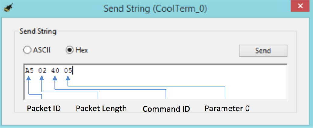
Step 4: Next, press CTRL+T (alternatively, go to Connection > Send String). When this window is open, select “Hex” and not “ASCII.” Now, input the command packet in the sequence specified. For this example, 0x05 was chosen for parameter ‘0’ to make the LED blink five times.
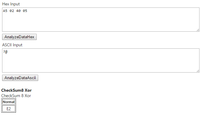
Step 5: Lastly, to input the LRC byte, it may be calculated using the XOR checksum calculator or any of the aforementioned methods in Section 12 – 5: Calculating the LRC Byte of this document. Copy the command packet string into the calculator and it should return the LRC byte as shown below.
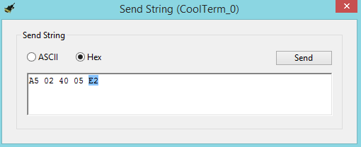
The LRC Byte should be the last byte in the command packet string in CoolTerm. Then, open the “Send String” window and click “Send” shown below. The onboard orange LED labeled “L” should blink five times if the command packet string is correct.

