Wireless Remote Communication Using XBee Radios
By Jake Rice
The Remote Control
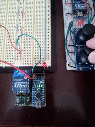
In order to meet the requirement of wireless communication between the UFO and the user, the UFO was equipped with an XBee radio. A remote control with 2 joysticks to enable the user to control the UFO was also equipped with an XBee radio. The joysticks control 2 10k-ohm potentiometers, with one for the vertical axis and one for the horizontal axis. Since the ADC has a maximum input voltage of 1.2 volts and the XBee reference voltage is 3.3 volts, a 22k-ohm resistor was placed in series with each potentiometer to limit the maximum input voltage to 1 volt.
Configuring the XBees
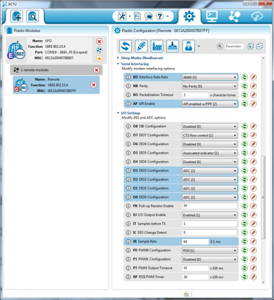
The two XBee radios were then configured to communicate with each other using XCTU. In order to communicate, two XBees must each have their destination address match the serial number of the other XBee. The UFO XBee must be set as a coordinator and the remote control XBEE must be set as an end device. To allow the XBee on the UFO to communicate serially with the Arduino, both XBees must be set to API (Application Program Interface) mode. IO pins 0-3 on the remote control XBee must be set to ADC mode to be used as inputs for the joysticks.
XBee Data
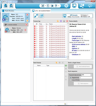
While the two XBEEs are communicating in API mode, the remote XBee sends the UFO XBee packets of data called frames. The length of the frame depends on the amount of data being sent, and with 4 inputs the remote XBee sends frames of 20 bytes. The first byte of the frame is always the start delimiter 0x7E, which is used to determine where each frame begins. Bytes 12-19 contain the data from the ADC inputs on the remote.
Interpreting the XBee Data
In order to isolate the potentiometer values from the incoming frame, the Arduino program waits until an entire frame’s worth of data (20 bytes) has been received. It then checks to make sure the first byte of the frame is the start delimiter (0x7E). Then, the program skips to byte 12, where the input data begins. Each potentiometer reading is represented by 2 bytes, high followed by low. The program multiplies the high byte of each reading by 256 and then adds the low byte to store each reading in a single variable.
Testing the Remote Control
As a test of the remote’s ability to control the speed of the UFO’s fans, the Arduino program was configured to read the vertical position of the bottom joystick. The range of possible values from that of the joystick’s neutral position to that of its highest position were mapped to the range of fan speeds from 0% to 100% of maximum thrust. The UFO was secured in place and both the UFO and the remote control were turned on. As the user moved the joystick up, the speed of the fans increased accordingly.