Spring 2016 A-TeChToP Central Sensor Suite Final Document
By: Cody Dunn (Project Manager)
Omar Rojas (Systems Engineer)
Stephen Cortez (Electronics Engineer)
Mimy Ho (Manufacturing Engineer)
Table of Contents
Executive Summary
Project Objective
The project objective is to design and implement an affordable and wearable sensor suite (A-TeChToP Central Sensor Suite) that allows for the safe and wireless real-time health monitoring of a child. A-TeChToP Central Sensor Suite will notify guardians when the child’s bio-signals have passed below or above healthy thresholds. The device must remove the need for standard encumbering medical equipment and minimize adult supervision.
This Central Sensor Suite must help monitor children with histories of
Asthma Exacerbation Frequent Fainting
Osteogenesis Imperfecta Juvenile Idiopathic Arthritis
Arrhythmias Frequent Fevers.
Mission Profile
A-TeChToP’s mission is to successfully monitor the illnesses stated in the project objective for a child between the ages of 5 and 13 while playing on a playground for thirty minutes. The Central Sensor Suite will be attached to the child’s chest and then the child will perform specific exercises and later play freely. Data will be sent continuously to a guardian-monitored computer and, if the child displays the symptoms of an illness, the guardian will be warned.
The device must be durable enough to withstand the small collisions and mild weather changes (light rain) associated with playground play.
A more detailed explanation of the mission profile can be found at: http://arxterra.com/spring-2016-a-techtop-detailed-mission-profile/
Level One and Level Two Requirements
The level one and two requirements stemmed from the Project Objective and Mission Profile above. It was important to establish a flow down from the customer’s desires to the Level One Requirements and then from the Level One Requirements to the Level Two Requirements. The requirements may be found at: http://arxterra.com/spring-2016-a-techtop-updated-level-1-and-2-requirements/
Overall Project Design
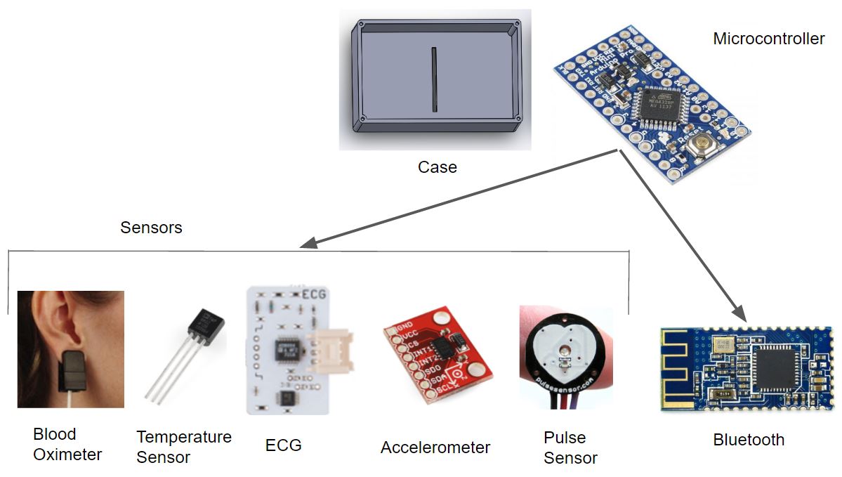
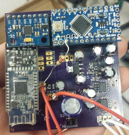
The overall design of the project features the five different types sensors seen controlled by the Arduino Pro Mini. The Bluetooth chip used for the project was the HM-10. The majority of the project was housed in a case, hence the name Central Sensor Suite.
Project Features
The project features five unique sensors for measuring the child’s health.
It features a modified control panel with images of the child’s orientation.
It has a custom-built ECG for monitoring the child in the convenience of one’s home.
The project utilizes the new threshold widget for alerting those monitoring the Arxterra Control Panel.
A custom harness design was build to work with the sensors.
The Arduino Pro Mini was used to decrease size.
The rest of the blog post will go into detail concerning the project features.
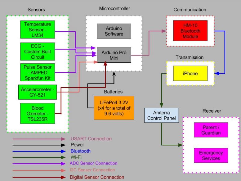
System Design
The final system block diagram is as shown below. The block diagram gives the specific sensors used and the connections between different parts of the device. The interface definition, fritzing diagram, and wiring diagram will go more into detail of how the connections are made on the Arduino, the wire placement throughout the device, and other interfacing information.
For each of the CSS sensors, there were project requirements that needed to be met in order to properly measure the desired vital signs of a child. For the ECG sensor, the design process began with testing electrode placement locations around the torso in order to understand how many electrodes are needed for a clear and visible ECG signal. It was found that using the Einthoven Triangle configuration, the group was able to acquire a clear signal that illustrated a subject’s heartbeat using only three electrodes. Next, it was researched that ECG signals are not only small, but susceptible to noise distortion from surrounding muscles and changes in skin impedance. These issues required solutions with the physical design of the harness to make secure electrode attachments to the subject as well as analog filtering. For analog filtering, the ECG signal was first run into an instrumentation amplifier IC, where it was along with some noise was amplified to a level that could be viewed on real-time plotters. Then, the signal was run through a highpass filter with a cutoff frequency of 3Hz in order to remove small baseline noise from skin impedance and poor electrode contact that would otherwise displace portions of the desired signal. Then, the signal passed through a lowpass filter with a cutoff frequency of 50Hz in order to remove muscle artifact noise that could potentially hide the entire ECG wave pattern if not addressed. Finally, the circuit used an operational amplifier to amplify and improve the visibility of the final signal so that it could be clearly displayed on a real-time plotter. Initially, the output from this configuration produced a readable ECG signal, but contained too much noise to be consistent and used for the final device product. Therefore, the group decided to improve the filtering so that the final signal would not exhibit any noise, be large enough to recognize the heartbeat wave patterns, and remain consistent overall. The highpass filter resistor and capacitor values were changed to 1Mohm and 1uF respectively, changing the cutoff frequency to 0.16Hz. This allowed the group to further remove any impedance noise that was remaining after the 3Hz cutoff frequency. Also, the lowpass filter values were changed to 4.3Mohm and 1000pF in order to make a cutoff frequency of 36Hz, which allowed the group to further remove artifact noise and allow the signal to be visible. Even though the lowpass filter does fairly well removing large noise interference, an additional Notch filter was added to the circuit at the end of the circuit.
The design requirements for the pulse oximeter include the necessity to accurately read the blood oxygen levels within a child during his or her playtime. This was met using a red LED, an IR LED, and the TSL235R sensor. Since oxygen within hemoglobin will absorb red and IR light differently, the two LEDs were placed on a thin portion of skin, with the IR constantly on and the red blinking every second. Measurements from the TSL235R were taken for each blink and also when the red LED was off in order to acquire the amounts of light absorbed by the amount of oxygen present within the child’s blood. A ratio was taken between the two values and the percentage of oxygen was then able to be calculated, with healthy values ranging from 95% to 99%.
More information concerning the sensors and experiments can be found at:
Subsystem Design
Interface Definition
The interface diagram as shown below is the final iteration. This is how the pins on the Arduino Pro Mini are utilized for our device. The interface definition shows which sensors are connected to which pin.
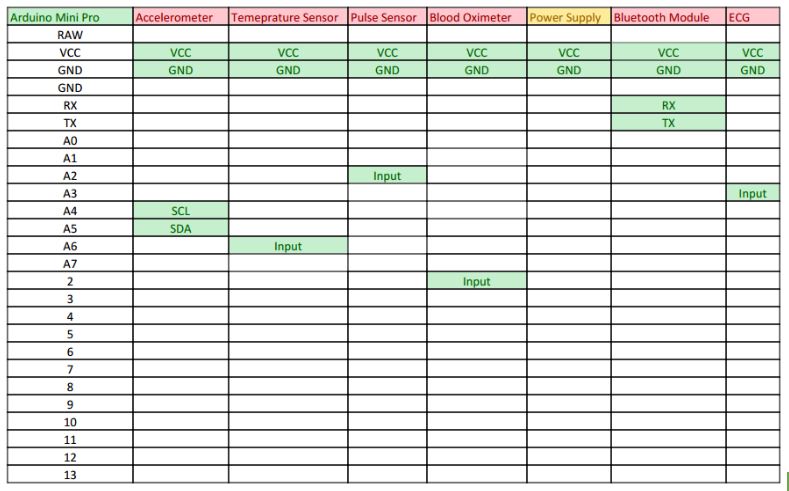
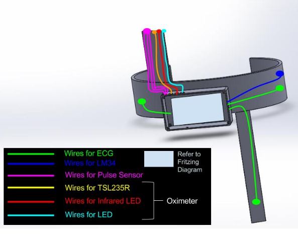
Following the interface definition is the wiring diagram. The wiring diagram shows how the wires will be placed throughout the device. The wiring diagram will show the placement of the sensors as well.
Custom PCB Design
The PCB is the central hub for the device and fully integrated. The PCB has the bluetooth HM10, accelerometer and the Arduino Pro Mini.
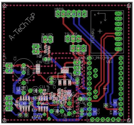
More information regarding the PCB layout can be found at: http://arxterra.com/spring-2016-a-techtop-pcb-layout/
Hardware Design
Temperature Sensor
An LM34 IC will be used to monitor child’s body temperature. This sensor will be placed on left side of the strap under the left arm. The pins of the sensor will be connected to the header on the other side of the strap where wires connects to the PCB. More information can be seen in the blog post: http://arxterra.com/spring-2016-a-techtop-final-hardware-design/
Pulse Sensor
The Sparkfun Pulse Sensor Amped will be used to measure a child heart’s beats. This sensor will be clipped to the right ear lobe by the clip on ear clip finding. The wires will be sewed the the shoulder strap of the harness and connecting to the PCB. The overall wires of the pulse sensor wires has similar view as the headphone wires.
Blood Oximeter
The prototype of the blood oximeter can be found in the blog post http://arxterra.com/spring-2016-a-techtop-final-hardware-design/
ECG Electrodes
The electrodes will be attached to the strap by using the snap on buttons. The wire is guided through the small hole and solder to make sure there is a good connection from the wire to the snap and the electrodes. More information can be found in the blog post http://arxterra.com/spring-2016-a-techtop-final-hardware-design/
3D Printed Case
The 3D printed case for the Central Sensor Suite device was designed to house the PCB and the battery. Holes were cut on the top, bottom, left and right side of the case for the wires to run from the PCB to the sensors and electrodes. The detailed of the 3D printed case can be found in the blog post: http://arxterra.com/spring-2016-a-techtop-3d-printed-case/
Software Design
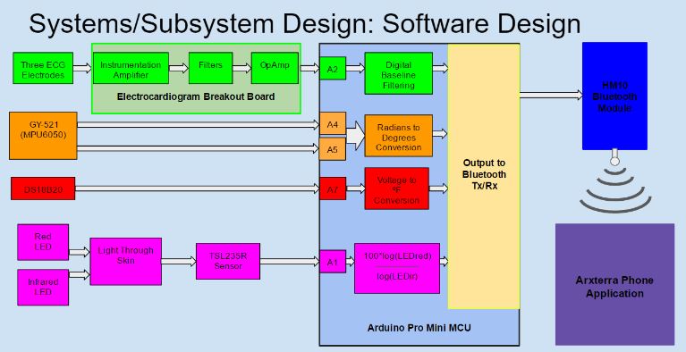
This above image provides a general block diagram of the software system. It is important to remember the overall goals and design when creating the Arduino software modules.
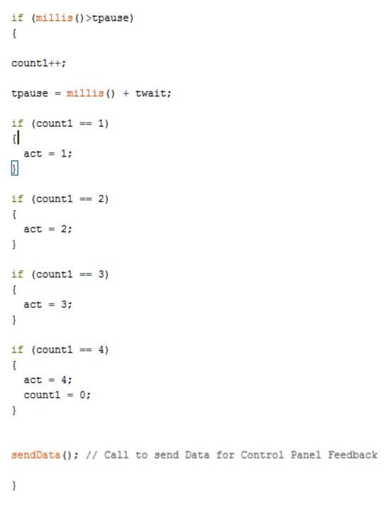
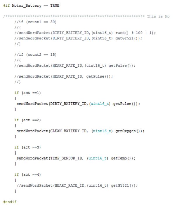
Telecoding and Encoding
The first section of code is how the delays are incorporated into the system as to not clogged the arxterra control panel while the second set of code shows how the information from the sensors are sent to the arxterra control panel.
Verification and Validation Test Plans
The verification and validation plans were made to ensure that our device satisfy the first and second level requirements. The plans list the objectives being met for that particular requirements and the steps needed to take to properly test it. We were able to satisfy a majority of the requirements. After going through the verification and validation plans, our device is properly working in conjunction with the sensors.
Project Update
Work Breakdown Structure
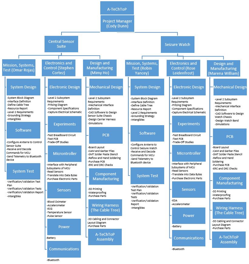
The WBS reflects the fact that the Project Manager was working on two different portions of the project. Each member’s tasks are clearly defined.
Resource Reports
The mass, power, and cost requirements were all met based on the given allocations. The detailed reports can be found in the CSS Systems Engineer Folder in the Dropbox from the resources sections of this blog post.
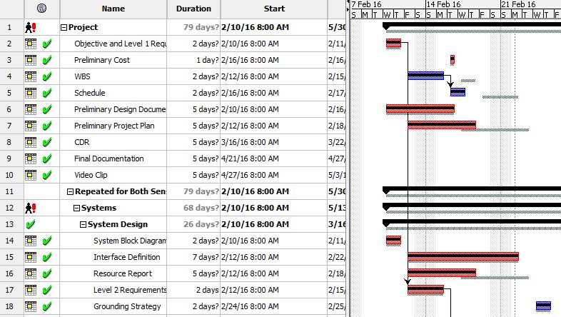
Schedule and Burndown
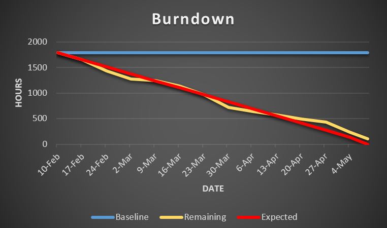
The project was 94% complete at the time of the final demonstration. The only missing portions were the thresholds on the Arxterra Control Panel (started but not completed), the waterproofing (not started), and the device could have gone through more rigorous testing. The device also should have had more digital filtering.
Key areas of slowdown included implementing the sensors and implementing unique Arxterra functions. Some of the slowdown was due to the fact that the code on the github for one of the old groups was not functional when tested and for the other group the page could not be found.
The group had to wrap up a large portion of the work in the final weeks because several tasks were started but not completed, which gave a false sense of security concerning the completion time. The group worked very hard after a poor CDR review to make up for lost time and complete the majority of the project. A video of the final demonstration can be found in the Dropbox Project Manager’s folder.
The schedule was created on Project Libre, which was only used because it is free. Otherwise, it is not easy to use. Here is a small part of the schedule to demonstrate the design that follows the WBS:
The project Burndown demonstrates the baseline work (blue), the completed work (yellow), and the expected work if the project was to be completed on time (red). The plot is in hours over time.
Concluding Thoughts
Improvements for the next generation:
- The next generation should focus on working to improve the data outputs and displays on Arxterra.
- They should also work on improving the durability of the device by printing with different materials.
- The form factor was significantly improved considering all of the sensors were run off of a central location. However, the thickness of the device should be decreased to allow the wearer to perform the trunk lift exercise. The current form factor was limited by the capacitors and batteries.
- Lastly, the device should be waterproofed and the wiring cleaned up for safety, durability, and aesthetics.
Lessons learned the hard way:
- It is extremely difficult to manage two teams no matter how similar the projects are initially thought to be.
- Group members will often provide verbal updates suggesting they are much farther along in their work. As project manager, it is important to confirm the work has been completed by requiring constant demonstrations at group meetings to determine the flaws outright.
- Make sure your members have thought through the design details by asking complicated questions concerning intangibles.
- It is important to push towards prototypes early in the semester even with the mass of initial blog posts.
- Remember that groups are trying to push for the best grade possible at the end of the semester. Some information concerning may have been falsified (intentionally and/or unintentionally).
How things should have been done differently:
- The division managers and project managers should have been in communication throughout the semester.
- More accountability should have been placed on the division managers to help complete projects as in the end it is one large company and company success is based on project completion.
- Groups must complete the proper research on past projects, not simply regurgitate information. Some old code may prove dysfunctional. If the group is relying on the code, it can be a major setback. Test old code at the start of the semester.
A more detailed analysis of concluding thoughts can be found at:
Resources
Final Video: https://www.youtube.com/watch?v=XQ16sDkx3aE
PDR: http://arxterra.com/spring-2016-a-techtop-preliminary-design-review/
The rest of the resources can be found in this Dropbox: https://www.dropbox.com/sh/9lg023uivp07bp8/AAAv6DZW-Dqmp9vylJc5koYqa?dl=0
The resources include but are not limited to
CDR (PDF)
Project Libre (with Excel Burndown file)
Verification and Validation documents
Solidworks File (zip folder)
Fritzing Files
EagleCAD files (zip folder)
Arduino and/or C++ Code (zip folder)
Complete Bill of Materials (BOM)