Spring 2017 BiPed – Final Blog Post
By: Alexander Clavel (Project Manager)
Project BiPed Team:
Alexander Clavel (Project Manager)
Jacob Cheney (Systems)
Abraham Falcon (Electronics & Control)
Mikaela Hess (Manufacturing)
Table of Contents
Executive Summary
Program Objective
The BiPed team was assigned the task of designing a 7th generation bipedal toy robot utilizing a 3Dot board. The robot was to use D.C. motors as the main driver for walking motion instead of the more frequently used servo based motion. Project Biped was to be able to demonstrate static walking and should be able to demonstrate the ability to dynamic walk and turn. Our project overall was to cost lest than $200.00 as well as be completed and ready to participate in the end of semester game on May 15th, 2017.
Mission Profile
The Biped shall be able to participate in the end of semester “Pacman” game where the goal is to navigate a maze while being remotely controlled. The velociraptor acts as the ghosts and attempts to catch up to the biped. If the biped is caught, then the velociraptor wins. There are also red colored dots placed around the maze that will count as points once a robot walks over it. The robot will then count the dot and continue on with the game. The time limit of the game lasts up to a maximum of 30 minutes. Viewing of the game will be provided by the spiderbot which will be hanging above the maze and relaying live video feed through the arxterra control panel. The game rules can be referred to here.
Project Features
Ankle Turning Servos
One of the main focus and key features of our robot is that we will use servos in the ankle to turn the robot. Traditionally when turning, you would change the speed at which the individual legs move reference to each other. You could have one leg moving while he other remains stationary or you can even have them rotate opposite of each other. For our design, none of the would work considering that we were using just one D.C. motor to power everything. Since we had one motor that rotate both legs simultaneously, we thought to get one leg off the ground and then to turn it from there. This proved to be an acceptable solution and perfect feature for our robot.
Tilt Box For Counterweight
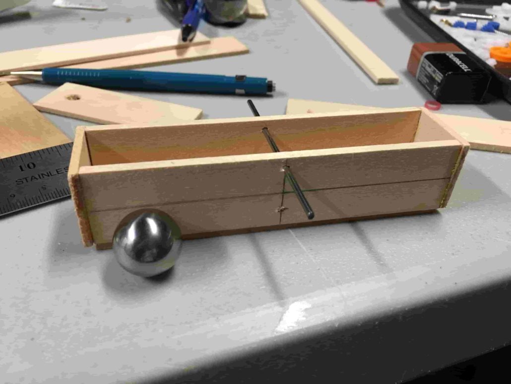
The other challenge for us was to be able to shift the center of mass of the robot to each leg as it would walk. Whenever a leg would lift up, the robot would immediately tilt over and fall. To attach this issue, we copied the idea from a Theo-Jansen video that was seen on the internet. The idea was to have a ball, or some sort of smooth weighted object move back and forth from side to side. The weighted object in question would obviously need to have weighed a majority of the entire systems weight to be able shift the center of mass, so mass allocations was a concern but we fell within requirements. In our design we incorporated a wooden box that would look like arms, and had a cam attached right beneath it to tilt the box back and forth effectively moving the ball back and forth.
This blog post goes more in depth with how the tilt box is essential to the robot.
http://arxterra.com/spring-2017-biped-working-prototypewalking-balancing-experiment/
Bluetooth Controlled Movement
The robot will be able to be controlled using the arxterra phone application or through a computer using the arxterra control panel. Due to the mission profile stating that we will be viewing game through a video, we needed to make the robot able to be controlled remotely. For our design we included a bluetooth module on the Arduino and from there was able to remotely control the BiPed. (3Dots were the planned component but through certain situations we were not able to use them and resorted to using an Arduino)
Simplistic/Straight Leg Design
For our robot we decided to go with a straight legged design instead of the more popular approach of using linkages. A few reasons for this is that we wanted to keep the robot as light as possible and as simple as possible. Adding linkages means more parts and more connections that need to be held together and ultimately adds more weight. More connections means more fasteners (or something of the sort) and the linkages would add material stress into consideration in more places than we intended. Keeping a straight leg would limit our focus on stress to only a few areas. We also essentially wanted to start over from scratch considering the last generation did not work with a D.C. motor source driven motion. If we were able to get it to walk, turn and succeed in all its functions, then the next class would be able to improve on it even more. It would be a lot more difficult for a class to try and find out what was wrong with the last one and improve it, than get a perfectly functioning one and improve it.
System Design
System Block Diagram
The system Block Diagram shows the inputs and outputs of our robotic system. From the input side we have the HM-10 Bluetooth module that receives data from the Arxterra application and an Adafruit color sensor that detects when the Biped is standing on a red surface. For outputs we have two servos and a DC motor that enable the robot to walk and turn. Lastly we have 3 LEDs to provide a visual effect. Two will be the “eyes” of the robot and one will be toggled on and off based on the color sensor inputs.
Subsystem Design
Experimental Results
We were able to test out and experiment on all the key components of our robot. The main concerns are all listed in this section of the blog post.
Servo Torque Test
D.C. Motor Stress Test
Color Sensor Experiment
Servo Turning Test
Interface Definition
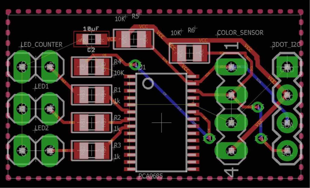
Custom PCB
The BiPed utilizes a total of 8 pins from the Arduino microcontroller. The left and right ankle servos are controlled by PWM pins 9 and 10 while the DC motor and color sensor are controlled by the I2C lines. Data will be transmitted through the Tx and Rx lines that are directly connected to the HM-10 Bluetooth module. All of the connected devices run off of the supplied 5V.
Mission Command and Control
Updated Software Block Diagram
The BiPed software contains six different subroutines. Five subroutines control the robots movements and one controls the color sensor and LED. The software begins by first decoding incoming data packets, then each subroutine is called based on the decoded command in the commandHandler
Electronics Design
Some of the main components to the robot would be the Pololu 200:1 D.C. motor. We chose this one specifically because it had high torque and would be able to move the robot even with all the weight we were placing on it. Further more, we only used one and that helped a lot with our mass allocations. There are other components such as HXT900 micro servos and a RGB color sensor. Additional information on the components can be found here.
Firmware
All of the code and firmware that was used to control the walking, turning, and color sensor can be found here.
PCB Schematic/Layout
We designed our PCB to be able to function modularly from the rest of the system. In short, the robot itself can still be able to perform its main function of walking and turning without it. The main purpose for the PCB was to be able to participate in the game. For that end, we needed the robot to be able to detect dots and to light up LEDs in accordance to those dots. Initially in our first design we had the PCB with many more functions. It had two more servos connected to it to serve as a way to shift the center of mass. Now that we are using a tilting box with moving ball bearings, that is no longer needed. It also adds to the simplicity of the design and allows us to keep everything as small and light weight as possible. Now that we have two less servos to deal with, it leaves more room for us on our mass allocations. The blog post above can provide more detail into the PCB.
Hardware Design
The above blog post is a show of one of the initial designs that we had previously had in mind. It again utilizes the straight leg, minimal linkage design. After progressing past this one we were able to look back on it and in retrospect really see where most of the flaws were coming from. Some of the key issues are as follows:
- Off-centered weight (D.C. motor sticking out of the body to the right)
- Unreliable pulley system
- Unacceptable leg design (overlapping)
- No center of gravity shift or consideration.
- Incorrect use of gear ratios (not specified in the blog post)
From these five lessons as well as others, we were able to come up with a better design and improve off the last one. The main difference with the newer design as opposed to the one before is that the dc motor is not centered in the middle. This makes it easier for balancing and the shifting of the center of mass. Now that most of the components are in the middle, the weighted ball can move from side to side at equal lengths. We also moved away from the pulley system completely. The blog post below as well as the images may provide better insight into the actual physical design.
Verification & Validation Test
We had written up our verification and validation in accordance to the new format which we had linked in the link below. The verification matrix is also included within the test plan and it documents all of the requirements that we were aiming to hit and those of which that we had not.
Verification & Validation Test Plan
Project Status
Power Allocation
The Table above shows the maximum current the robot can draw at one particular time. This would mean both servos and the DC motor are at full power. The max current draw is 600 mA with a 60 mA margin. Our battery can only supply around 650 mA at a given time so this means our contingency is actually negative. While this may seem bad, its an impossible scenario because our robot will never be running all 3 actuators at one time.
This table shows the max current of each actuator with the total capacity of our battery. The goal here is to ensure the battery has enough energy to power the Biped for at least 30 minutes. Since the robot will only be using one actuator at a time, the worst case scenario would be the Arduino (200 mA) and the DC motor (100 mA) running at full power. At 300 mA our battery is rated with a total capacity of 400 mAh. This means our robot will be able to supply power much longer than our desired minimum.
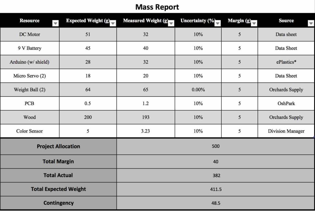
Mass Allocation
Cost Report
| Receipt | Vendor | Item | Unit Price | Quantity | Total Cost (Including Shipping) | Purchased By |
| 1 | Pololu | 200:1 Plastic Gear Motor | 5.75 | 1 | 23.70 | Abraham Falcon |
| 2 | Adafruit | RGB Color Sensor w/ IR Filter and White LED – TCS34725 PID: 1334 | 7.95 | 1 | 23.94 | Abraham Falcon |
| 3 | Mouser | 1 K Ohm Thick Film Resistor | 0.10 | 3 | 0.30 | Abraham Falcon |
| 3 | Mouser | Standard LEDs (Red Diffused) | 0.360 | 2 | 0.72 | Abraham Falcon |
| 3 | Mouser | Standard LEDs (Green Diffused) | 0.360 | 1 | 0.36 | Abraham Falcon |
| 3 | Mouser | 10 uF Multilayer Ceramic Capacitors | 0.60 | 1 | 0.60 | Abraham Falcon |
| 3 | Mouser | 10 K Ohm Thick Film Resistor | 0.10 | 3 | 0.30 | Abraham Falcon |
| 3 | Mouser | Semiconductors I2C Bus LED / LED Display Drivers | 2.31 | 1 | 2.31 | Abraham Falcon |
| 3 | Mouser | Molex KK 100 Hdr Assy Bkwy / Headers and Wire Housing | 0.27 | 2 | 0.54 | Abraham Falcon |
| 3 | Mouser | Molex BREAKAWAY HDR VERT 2 / Headers and Wire Housing | 0.16 | 3 | 0.48 | Abraham Falcon |
| 3 | Mouser | (Shipping+Tax) | 19.83 | 1 | 19.83 | Abraham Falcon |
| 4 | Home Depot | Acrylic Sheet | 10.27 | 1 | 11.17 | Alexander Clavel |
| 5 | Staples | Staedtler Math Zip | 4.99 | 1 | 4.99 | Alexander Clavel |
| 5 | Staples | Loctite Liquid Super Glue | 5.99 | 1 | 5.99 | Alexander Clavel |
| 6 | Amazon | 120 Pc RC Parts Lot (Plastic Gears, Pulley…) | 13.95 | 1 | 19.94 | Alexander Clavel |
| 7 | Amazon | Geebot Pulley Combination Package | 9.99 | 1 | 9.99 | Alexander Clavel |
| 7 | Amazon | Ajax Scientific Plastic Loose Pulley, 50 mm Diameter | 8.52 | 1 | 8.52 | Alexander Clavel |
| 7 | Amazon | Ajax Scientific Plastic Loose Pulley, 25 mm Diameter | 8.21 | 1 | 8.21 | Alexander Clavel |
| 7 | Amazon | (Shipping +Tax) | 7.81 | 1 | 7.81 | Alexander Clavel |
| 8 | Amazon | 2 of HXT900 9g Micro Servo | 6.49 | 1 | 12.98 | Alexander Clavel |
| 9 | Amazon | 120 Pc RC Parts Lot (Plastic Gears, Pulley…) | 13.95 | 1 | 13.95 | Alexander Clavel |
| 9 | Amazon | 10 PCs 2mm Dia 250mm Length Stainless Steel Rod Shaft | 7.51 | 1 | 7.51 | Alexander Clavel |
| Total: | 184.14 | Budget Allocation:
200.00 |
Updated Schedule
Top Level
Subsystem
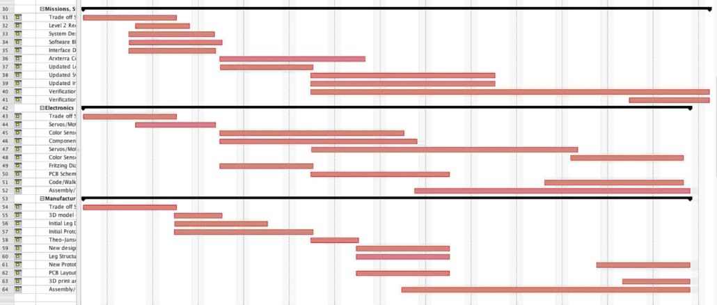
Much of the top level schedule had remained the same mostly because most of the top level tasks had been completed. In the subsystem schedule you can see that some of the tasks mainly in electronics and control and in manufacturing had been pushed back some. This was mostly due to manufacturing’s inability to be able to produce and assemble a working prototype.
Burndown and Percent Complete
The project ended up being rushed at the end but we were able to finish on time. There were many bumps along the road like components not working, or accidental drops that hindered the progress of the project as a whole but in the end we were able to finish everything on time.
Summary / Concluding Thoughts
Results
In the end the project was completed on time. We were able to create a statically walking BiPed that was bluetooth remotely controlled and was able to turn up to 180 degrees. We stayed within budget costs and weight limits that were set. The only issue was that nearing the demonstration date, the BiPed was dropped and the timing for the tilt box was thrown off and ultimately threw off the entire walking motion. We continuously tried to solve the problem before demonstrating it, but we ended up running out of time. Although it did not walk on the actual day of the demonstration, we are happy that we were able to get a fully functional system running and working exactly as we had intended it to. We can strongly say that this is a strong base for the next class to try and improve on it especially because it is a system that works.
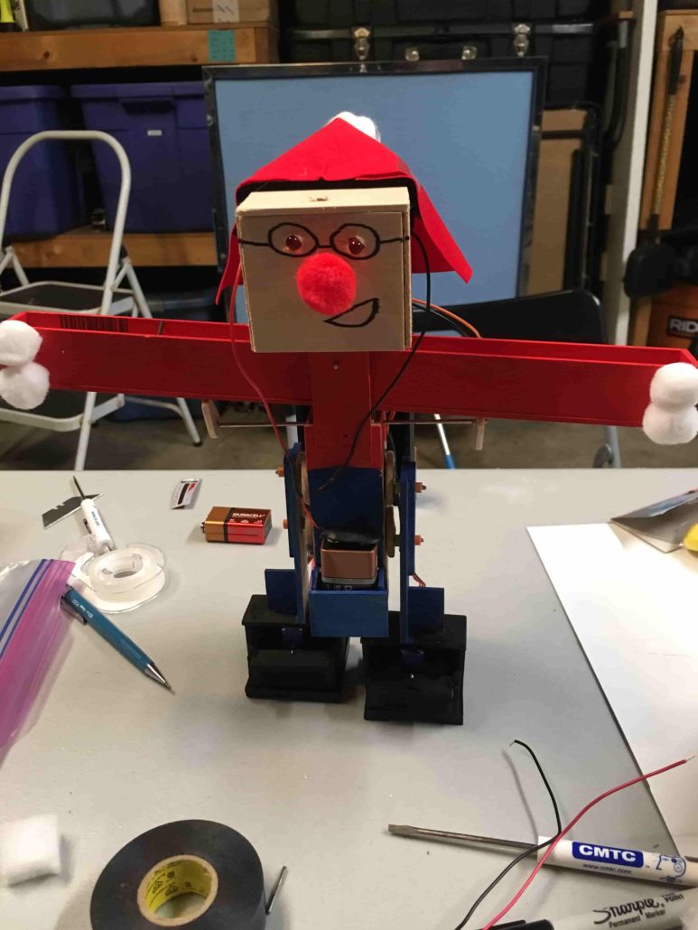
We also ended up running out of time because we had planned to laser cut the entire body our of plastic and to make it look sleek and nice. Due to being rushed and having limited time for testing, this was not able to happen. We had, at the end, printed out the head unit, body, and legs, but had not completed the tilting box, cams for the box, and the servo brackets to hold the feet. Ultimately it ended up looking like an evil Santa Claus due to the request of the customer wanting it to be more “toy-like” and fun looking.
The two different videos below show the BiPed in 2 different stages of its development. The first video shows the BiPEd with minimal weight on it and purely tests the functionality of it’s ability to turn and walk forward. The second video is in the final stages of its production and has (for all intents and purposes) the amount of weight that it would normally carry. In this test we decided to test out one of the requirements that it be bluetooth controlled from a distance of 5 feet. Jacob in the background is controlling the BiPed as it walks forward from a measure distance of 5 feet. All of this shows the success of the project in itself.
Video 1
Video 2
Lessons Learned/Future Suggestions
******THIS IS A MECHANICALLY CHALLENGING PROJECT*******
When you look at this project as a whole, we are studying to become electrical engineers and in all honesty do not focus too much on the physical aspects of a system. Granted, we have our basic physics courses and knowledge, but we are not experts on the mechanics of robots. That being said, manufacturing division must be a huge focus of the project managers from the beginning of the semester. From the very beginning you need to focus on getting a system that is structurally sound and something that works. If you cannot do that then, it does not matter how amazing of an electrical engineer you or any of your teammates are. If you cannot produce a testable system that is structurally sound, you will not be able to progress at all. The issue that I ran into with my project group was that at the time that my systems and electronics engineers were ready to test, my manufacturing had not yet produced a testable model. This was where the brunt of our time was spent. More time should have gone into studying and researching how to actually design the physical aspects of the robot. The assumption was that it was going to be quick and easy was one of our biggest downfalls.
The other very destructive aspect of our project process was that we spent much too long in the “creative” aspect of our design. There were many times where we keep throwing out ideas that we thought would be “cool” or innovative where instead we should have stuck to one idea, one solution and worked on it from there. There were three specific times where we worked an initial design and then from there, we thought of “a better way to do it”. We then scrapped the first option and completely started anew with the next one. This happened 3 times and it pushed us far back past our schedule than I had originally intended. This leads into the role as the project manager. Sometimes you just have to push your engineers. You cannot be worried about them liking you and you cannot have things be personal between you and your team. The project is a team effort and everyone has to do their part. If someone is slacking you have to be able to tell them in a firm manner that they are not performing the way that they should be. I made the mistake of trying to be too nice. I feel that in doing that, it gave certain individuals the idea that they were able to push due dates back on me. The difficult part that you will have to figure out on your own is being able to discern that sensitive line between destroying their motivation to do any work, and the firm hand that will keep them doing their job.
Lastly, when it really comes down to it and there is no other option, the project manager must step in to get the job done. There may be a time where a certain division is not doing their job and no matter what you do, they just do not improve or produce acceptable work. It is at that time that you must step in and just complete the work yourself. Whether you do that by getting help from the other division members/manager, or you step in to do the work yourself. As the project manager, results and ultimately mission success falls completely on you. Yes you may find a fault in one of your divisions, and yes it may be clear where things went wrong, but you are the one who’s job it is it make sure those don’t happen. I found myself in the situation where I waited to long to do just that. I could not wait any longer and I had to step in to build the physical aspect of the robot myself. It was done with just enough time, but it was a stressful and extremely arduous process. If I was able to identify the problem sooner and stepped in sooner, we may have been able to get in a few more tests than we had actually completed. We may have been able to make the robot more durable and last longer. The point is that you are ultimate quality control and the performance and quality of the project rests on you.
In summary:
- Focus on the physical robot mechanics and structural aspects
- Do the research, and not just when you think it is enough (Continually question your design for flaws)
- Do not jump around on options. Once you have picked a design, stick with it until you have exhausted all solutions
- Push project members to do their job
- Quality control the work that is being done by your members
- BE PREPARED TO STEP IN AND DO ANY JOB THAT IS REQUIRED

